Lower processor board (MB) switches
The following illustrations show the location of the switches on the lower processor board (MB).
Before you change any switch settings or move any jumpers, turn off the server; then, disconnect all power cords and external cables. Review the following information:
- Any lower processor board (MB) switch or jumper block that is not shown in the illustrations in this document are reserved.
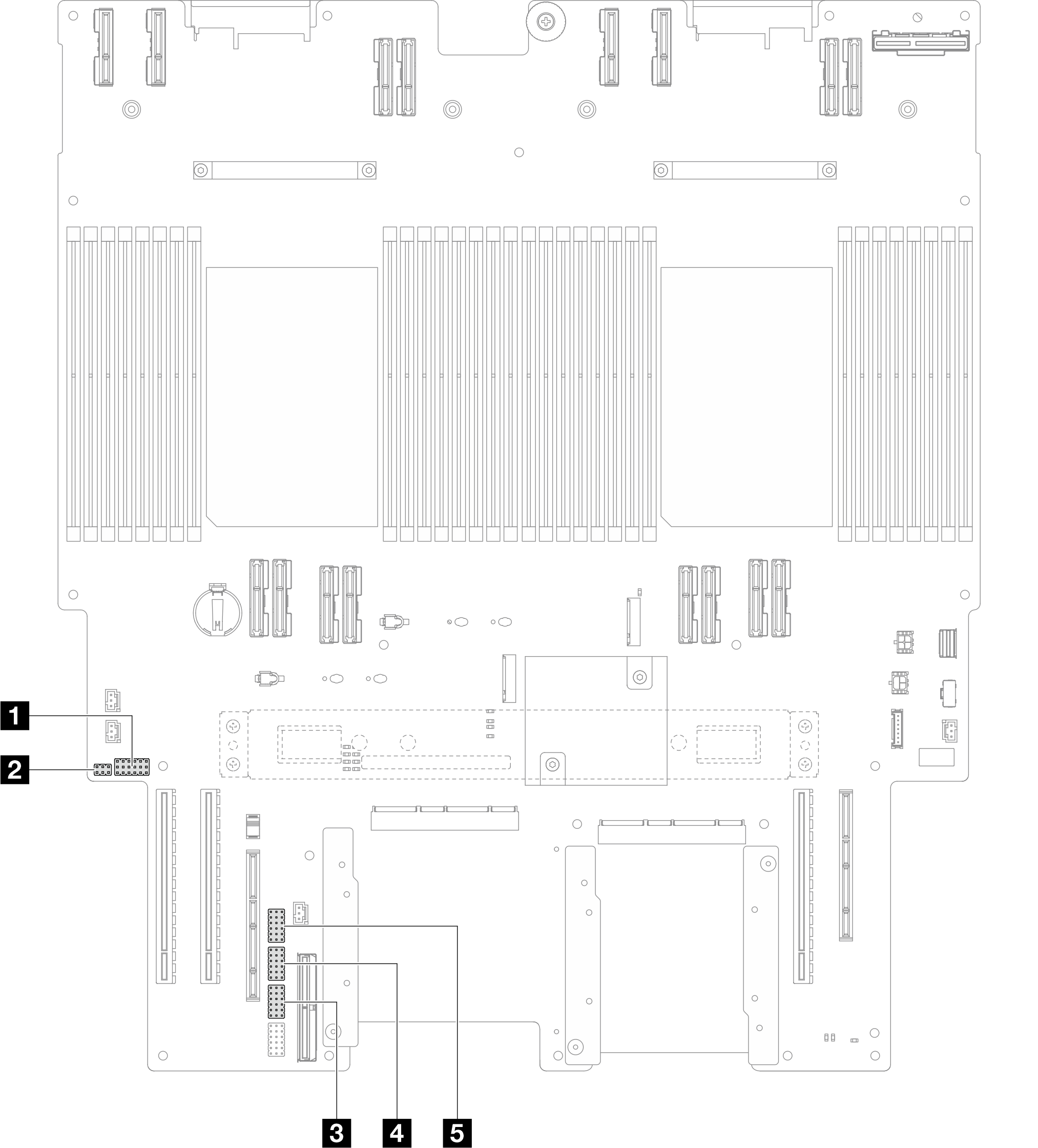
| 1 J201 | 4 J117 |
| 2 PJ1 | 5 J191 |
| 3 J02 |
J201 switch block
Location | Jumper Name | Position | Function |
|---|---|---|---|
J201A | Reserved | 1-2 (Default) | Reserved |
2-3 | Reserved | ||
J201B | Reserved | 1-2 (Default) | Reserved |
2-3 | Reserved | ||
J201C | Reserved | 1-2 (Default) | Reserved |
2-3 | Reserved | ||
J201D | Reserved | 1-2 (Default) | Reserved |
2-3 | Reserved | ||
J201E | CMOS clear | 1-2 (Default) | Off |
2-3 | Resets the RTC. A momentary toggle is all that is required. To avoid excessive CMOS battery drain, do not leave this switch in the On position. | ||
J201F | Reserved | 1-2 (Default) | Reserved |
2-3 | Reserved |
PJ1 switch block
Location | Jumper Name | Position | Function |
|---|---|---|---|
PJ1A | Reserved | 1-2 (Default) | Reserved |
2-3 | Reserved | ||
PJ1B | Reserved | 1-2 (Default) | Reserved |
2-3 | Reserved |
J02 switch block
Location | Jumper Name | Position | Function |
|---|---|---|---|
J02A | Reserved | 1-2 (Default) | Reserved |
2-3 | Reserved | ||
J02B | Password clear | 1-2 (Default) | Normal |
2-3 | Overrides the power-on password. Changing the position of this switch does not affect the administrator password check if an administrator password is set. | ||
J02C | Reserved | 1-2 (Default) | Reserved |
2-3 | Reserved | ||
J02D | Reserved | 1-2 (Default) | Reserved |
2-3 | Reserved | ||
J02E | Reserved | 1-2 (Default) | Reserved |
2-3 | Reserved | ||
J02F | Reserved | 1-2 (Default) | Reserved |
2-3 | Reserved |
J117 switch block
Location | Jumper Name | Position | Function |
|---|---|---|---|
J117A | Reserved | 1-2 | Reserved |
2-3 (Default) | Reserved | ||
J117B | Reserved | 1-2 | Reserved |
2-3 (Default) | Reserved | ||
J117C | ME FW update | 1-2 (Default) | Normal |
2-3 | Enable ME boot to recovery. | ||
J117D | Flash security override | 1-2 (Default) | Disable flash security override. |
2-3 | Enable flash security override. | ||
J117E | Reserved | 1-2 (Default) | Reserved |
2-3 | Reserved | ||
J117F | Reserved | 1-2 (Default) | Reserved |
2-3 | Reserved |
J191 switch block
Location | Jumper Name | Position | Function |
|---|---|---|---|
J191A | Reserved | 1-2 (Default) | Reserved |
2-3 | Reserved | ||
J191B | Reserved | 1-2 | Reserved |
2-3 (Default) | Reserved | ||
J191C | Reserved | 1-2 (Default) | Reserved |
2-3 | Reserved | ||
J191D | Reserved | 1-2 | Reserved |
2-3 (Default) | Reserved | ||
J191E | Reserved | 1-2 (Default) | Reserved |
2-3 | Reserved | ||
J191F | Reserved | 1-2 (Default) | Reserved |
2-3 | Reserved |