Cabling the network
Review the following information to understand how to cable the ThinkAgile VX appliances to the network.
Logical network design for deployment
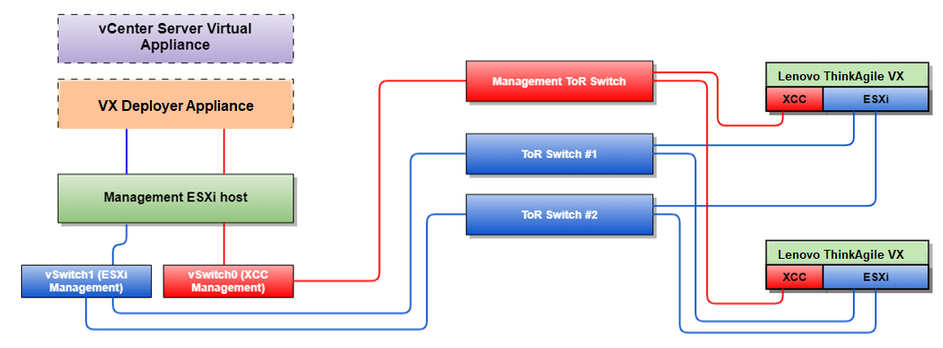
Figure 1 shows the logical network architecture for the various components in the vSAN cluster deployment.
Figure 3 shows details about physical cabling.
The VX Deployer Appliance is a virtual machine that can run on the VMware vSphere ESXi hypervisor. In the diagram, the Management ESXi host is a designated system on which various management appliances run, including Lenovo xClarity and vCenter Server Appliance (VCSA).
In a preloaded ThinkAgile VX appliance, the VX Deployer virtual appliance is preloaded on the VX appliance. In this case, the Deployer will be running on one of the VX appliances and the cluster deployment will be performed from there.
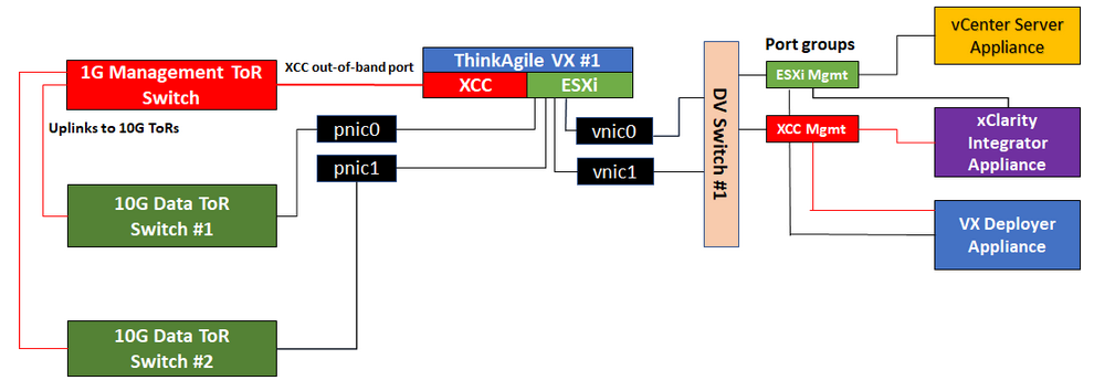
Each VX series and FX series with VMware server has dedicated connections to the onboard 10 Gbps Ethernet ports used for in-band management (ESXi management, vCenter, etc.).
The XClarity Controller (XCC) interfaces have dedicated connections for out-of-band management access.
The VX Deployer virtual appliance needs access to the ESXi management and XCC management networks via the virtual switches. Therefore, the respective port groups on the switch should be configured.
Physical network cabling
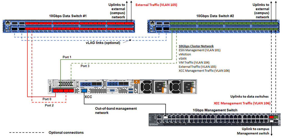
| Network type | Required/optional | From | To |
In-band management network:
| Required | Port 0 on NIC | 10 Gbps Data Switch #1 |
| Required | Port 1 on NIC | 10 Gbps Data Switch #2 | |
| Optional | Port 2 on NIC | 10 Gbps Data Switch #1 | |
| Optional | Port 3 on NIC | 10 Gbps Data Switch #2 | |
Out-of-band management network:
| Required | BMC network connector | 1 Gbps Management Switch |
| Data or user network | Required | 10 Gbps Data Switch #1 and #2 | External network |
On Out-of-band network
The out-of-band management network does not need to be on a dedicated physical network.It can be included as part of a larger management network.
The ThinkAgile VX Deployer, Lenovo XClarity Integrator (LXCI) must be able to access this network to communicate with the XCC modules.
During the initial cluster deployment and subsequent operations, the XCC interfaces should be accessible over this network to the VX Deployer as well as to xClarity Integrator (LXCI), xClarity Administrator (LXCA), etc., management software.
If a VLAN is used for the out-of-band network, the native VLAN must be configured on the physical switches for the out-of-band ESXi network ports.
Make sure that IPv6 is enabled in XCC under , and no IPv6 traffic restrictions are applied on BMC network VLAN.
On In-band network
If a VLAN is used for the in-band network, the native VLAN must be configured on the physical switches for the in-band ESXi network ports.
A maximum transmission unit (MTU) of 9000 must be configured on the physical switches for the in-band ESXi network ports.
On network redundancy
Active-standby redundancy mode:
When only 2 ports (ports 0 to 1) are connected to the 2 top-of-rack switches, you can configure the redundancy mode as active-standby mode. If the primary connection fails or the primary switch fails, the connection fails over.
Active-active redundancy mode:
When 4 ports (ports 0 to 3) are connected to the 2 top-of-rack switches, you can configure the redundancy mode as active-active mode. If one connection fails, the other connections are still active. Also, loads are balanced across the ports.
Optionally, some switches might also support the virtual link aggregation (vLAG) protocol or equivalent, which connects the two top-of-rack switches via dedicated links and makes the switches appear as a single logical switch to the downstream hosts. In this case, the two connections going to the switches from the host can be configured as active-active links so that you can get load-balancing across the ports as well as a 20 Gb aggregate bandwidth.
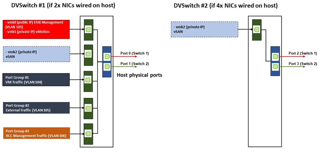
Distributed vSwitches
The VX Deployer will create Distributed vSwitches when installing the VX/vSAN cluster.
The distributed vSwitches essentially form a logical switch that spans all hosts in the cluster. The physical ports on each host become logical uplink ports on the distributed vSwitch. As opposed to a standard vSwitch, distributed vSwitches provide advanced configuration options, such as traffic policy, link aggregation (LACP), and traffic shaping.
The number of created distributed switches is determined by the number of physical ports on each host that are connected to top-of-rack switches:
If only two ports on each host are connected, a single distributed vSwitch will be created to carry all types of traffic, including ESXi management, vMotion, internal VM, XCC management, vSAN storage traffic, and external network traffic.
If four ports are connected, two distributed vSwitches will be created. The vSAN storage traffic will be carried on the second distributed vSwitch.
Figure 4 shows the logical design of the distributed vSwitches that will be created by the VX Deployer.