System Management Module 3 (SMM 3)
The following illustration shows the connectors and buttons on the SMM3 module.
SMM3 connectors
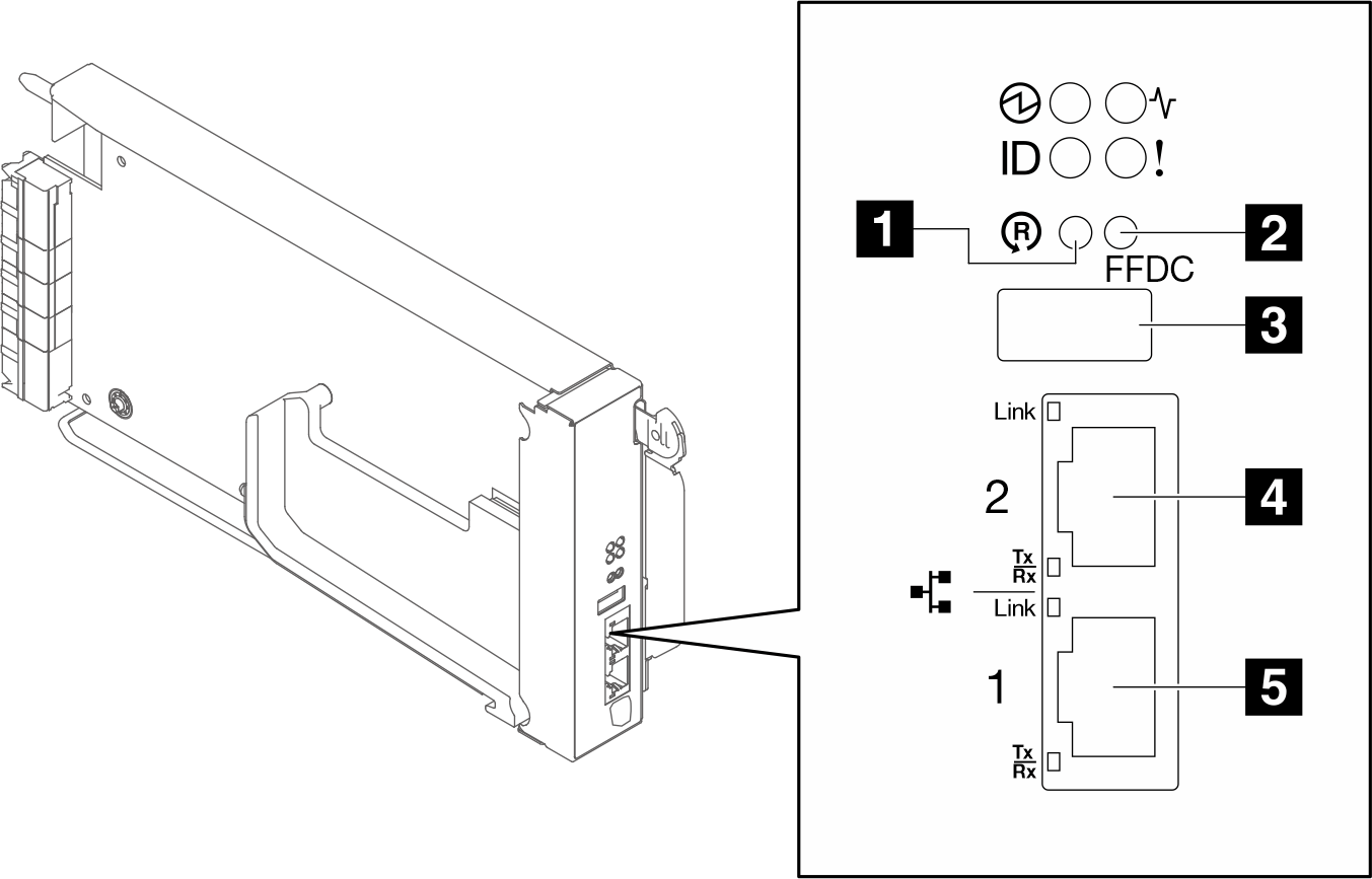
1 Reset button: Press the button for 1 to 4 seconds, SMM3 reboots. Press over 4 seconds, SMM3 reboots and loads to the default settings.
2 USB port service mode button (FFDC dump): Press this button to collect FFDC logs after inserting the USB storage device to the USB 2.0 connector.
3 USB 2.0 connector: Insert the USB storage device to this connector and then press the USB port service mode button to collect FFDC logs.
4 Ethernet port 2: Use this connector to access SMM3 management.
5 Ethernet port 1: Use this connector to access SMM3 management.
The SMM3 management module has two Ethernet ports which allows a single Ethernet connection to be daisy chained across 3 enclosures and 48 nodes, thereby significantly reducing the number of Ethernet switch ports needed to manage an entire rack of SC750 V4 trays and N1380 enclosures
It is recommended to use SMM3 Ethernet port as the default dedicated management network. If required to use node front Ethernet port as dedicated management network, refer to XCC user guide for network configuration instructions.
SMM3 LEDs
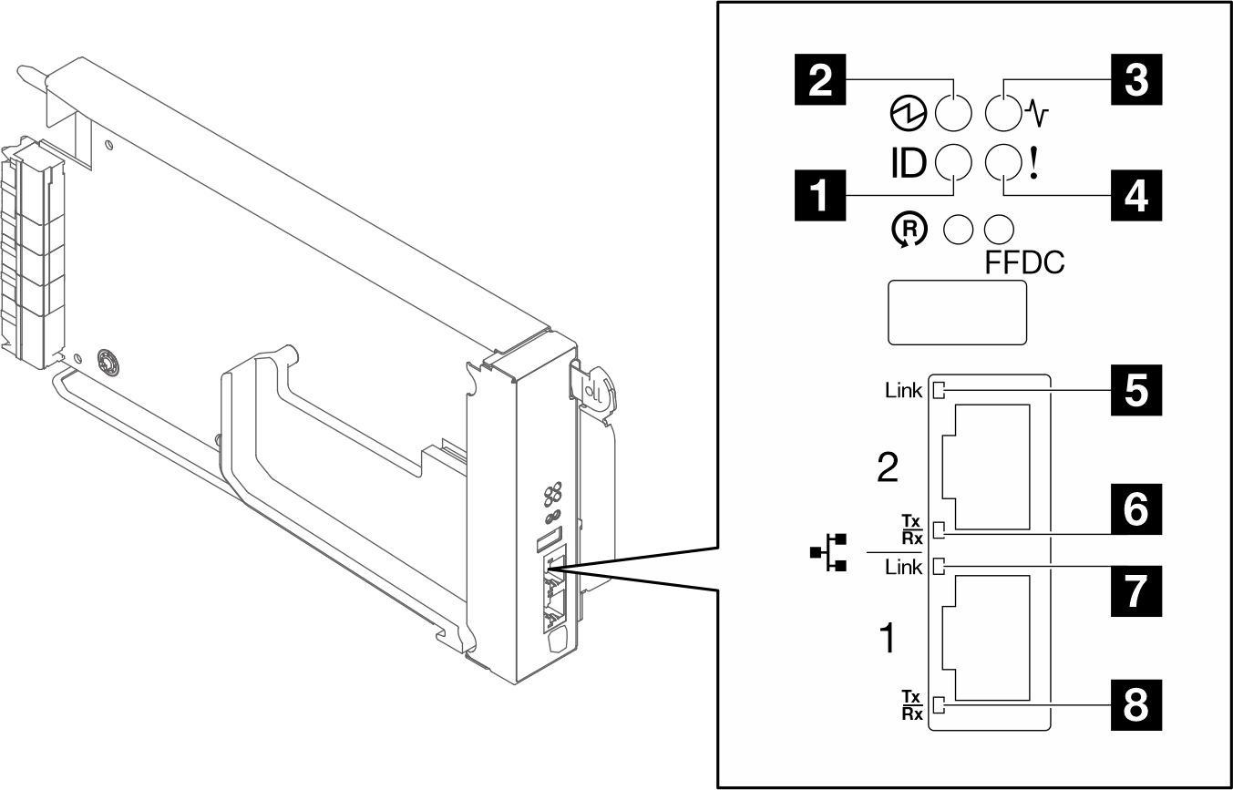
| 1 Identification LED (blue) | 5 Ethernet port 2 link (RJ-45) LED (green) |
| 2 Power LED (green) | 6 Ethernet port 2 activity (RJ-45) LED (green) |
| 3 Status LED (green) | 7 Ethernet port 1 link (RJ-45) LED (green) |
| 4 Check log LED (yellow) | 8 Ethernet port 1 activity (RJ-45) LED (green) |
1 Identification LED: When this LED is lit (blue), it indicates the enclosure location in a rack.
2 Power-on LED: When this LED is lit (green), it indicates that the SMM3 has power.
Continuously on: The SMM3 has encountered one or more problems.
Off: When the enclosure power is on, it indicates the SMM3 has encountered one or more problems.
- Flashing: The SMM3 is working.
During the pre-boot process, the LED flashes at 1 Hz then change to keep on.
LED flashes at 1 Hz: the SMM3 hardware is working and ready to initialize.
LED keeps on: SMM3 is initializing.
When the pre-boot process and initialization are completed and the SMM3 is working correctly, the LED flashes at 1 Hz (once every second).
4 Check log LED: When this LED is lit (yellow), it indicates that a system error has occurred. Check the SMM3 event log for additional information.
5 Ethernet port 2 link (RJ-45) LED: When this LED is lit (green), it indicates that there is an active connection through the remote management and console (Ethernet) port 2 to the management network.
6 Ethernet port 2 activity (RJ-45) LED: When this LED is flashing (green), it indicates that there is an activity through the remote management and console (Ethernet) port 2 over the management network.
7 Ethernet port 1 link (RJ-45) LED: When this LED is lit (green), it indicates that there is an active connection through the remote management and console (Ethernet) port 1 to the management network.
8 Ethernet port 1 activity (RJ-45) LED: When this LED is flashing (green), it indicates that there is an activity through the remote management and console (Ethernet) port 1 over the management network.