System-board connectors for cable routing
See this section to locate and identify the connectors on the system board that are used for internal cable routing.
Figure 1. System-board connectors for cable routing
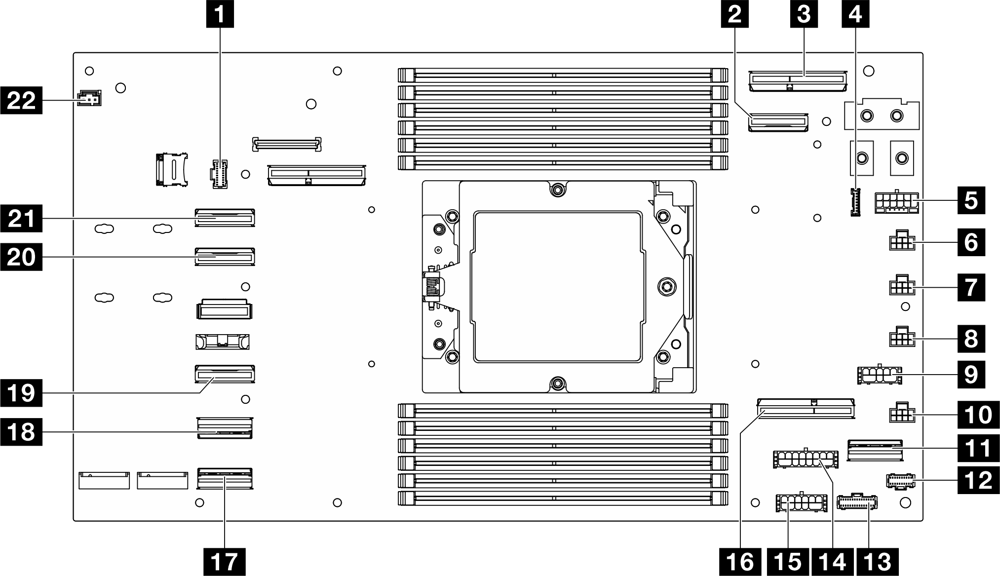
| 1 Drive backplane or front I/O sideband connector | 12 M.2 boot adapter connector |
| 2 OCP power and sideband connector | 13 PDB sideband connector |
| 3 OCP connector | 14 Riser power connector |
| 4 Leakage sensor module cable connector | 15 PDB auxiliary power connector |
| 5 Drive backplane power connector | 16 Riser slot 1 connector |
| 6 Fan 1 connector | 17 Rear I/O connector |
| 7 Fan 2 connector | 18 SATA 0-5 connector |
| 8 Fan 3 connector | 19 NVMe 4-5 connector |
| 9 RAID power connector | 20 NVMe 2-3 connector |
| 10 Fan 4 connector | 21 NVMe 0-1 connector |
| 11 RAID signal connector | 22 Inlet temperature sensor connector |
Give documentation feedback