Remove the front OCP cage
Follow instructions in this section to remove to remove the front OCP cage.
About this task
To avoid potential danger, make sure to read and follow the safety information.
Attention
Read Installation Guidelines and Safety inspection checklist to make sure that you work safely.
Procedure
- Make preparations for this task.
- Power off the node (see Power off the node); then, disconnect all external cables from the node.NoteIf necessary, press the release clip with a flat-head screwdriver to remove an external network cable from the rear of a 2U node.

- Power off the node (see Power off the node); then, disconnect all external cables from the node.
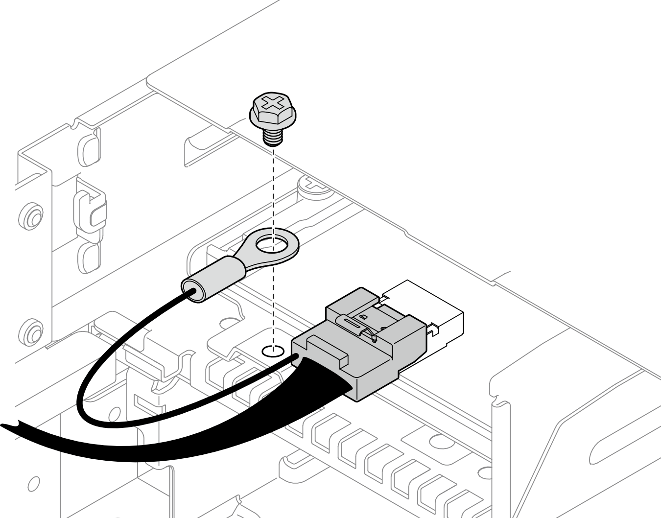
- Loosen the screw that secures the grounding cable; then, remove the grounding cable from the front OCP cage.Figure 1. Screw of the front I/O grounding cable
- Remove the front OCP cage from the node.
 Remove all the screws that secure the cage to the node on the left and right sides of the node.
 Disconnect the XCC management module cable from the OCP cage.
 Remove the two screws that secure the front OCP cable to the OCP cage (1 in the illustration). Then, disconnect the shorter OCP cable (1a in the illustration) from the system board and lift this cable away from the front air baffle.NoteTo prevent damage on the OCP cable, avoid using excessive force on the OCP cable screws.
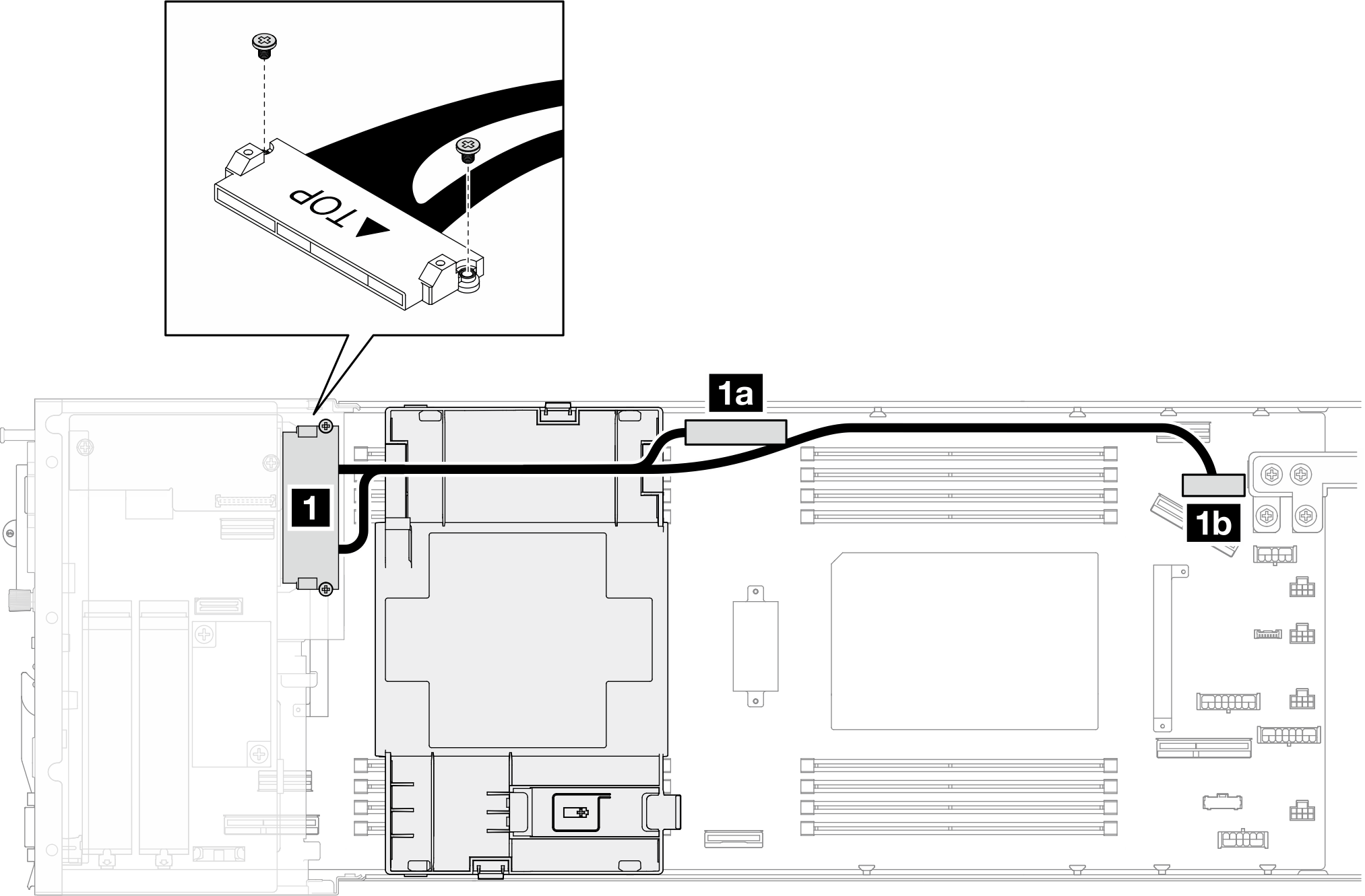
1 Front OCP cable screws 1a Shorter front OCP cable 1b Longer front OCP cable  Push the cage toward the front of the node.
 Lift the cage out of the node.Figure 2. Removal of the front OCP cage
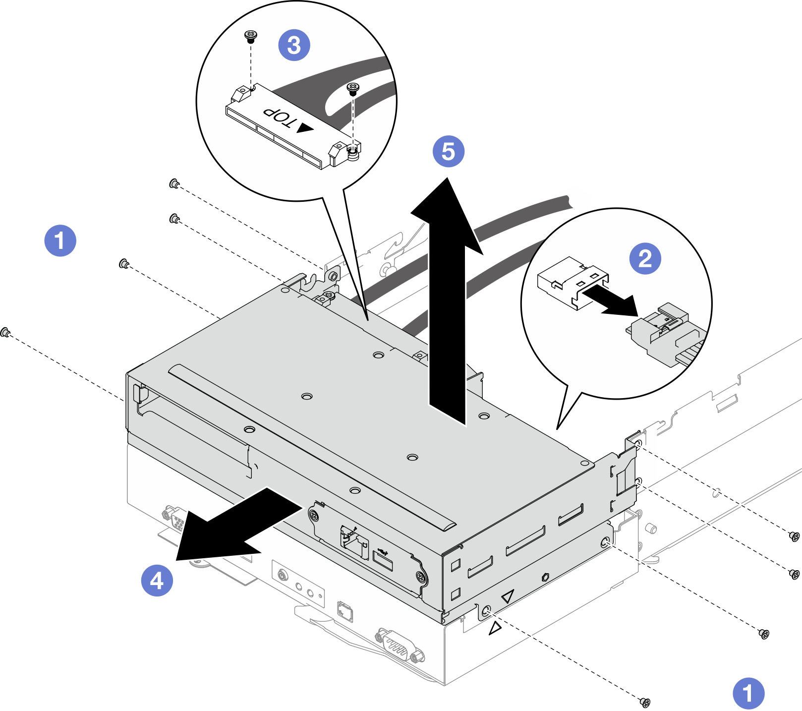
After you finish
- Install a replacement unit (see Install a front OCP cage).
- If you are instructed to return the component or optional device, follow all packaging instructions, and use any packaging materials for shipping that are supplied to you.
Demo video
Give documentation feedback