Install a processor-heat-sink module
The processor and heat sink are removed together as part of a processor-heat-sink-module (PHM) assembly. PHM installation requires a Torx T30 driver.
About this task
Read the Installation Guidelines to ensure that you work safely.
Prevent exposure to static electricity, which might lead to system halt and loss of data, by keeping static-sensitive components in their static-protective packages until installation, and handling these devices with an electrostatic-discharge wrist strap or other grounding system.
Each processor socket must always contain a cover or a PHM. When removing or installing a PHM, protect empty processor sockets with a cover.
Do not touch the processor socket or processor contacts. Processor-socket contacts are very fragile and easily damaged. Contaminants on the processor contacts, such as oil from your skin, can cause connection failures.
Do not allow the thermal grease on the processor or heat sink to come in contact with anything. Contact with any surface can compromise the thermal grease, rendering it ineffective. Thermal grease can damage components, such as the electrical connectors in the processor socket.
Remove and install only one PHM at a time. If the system board supports multiple processors, install the PHMs starting with the first processor socket.
Figure 1. Processor locations on system board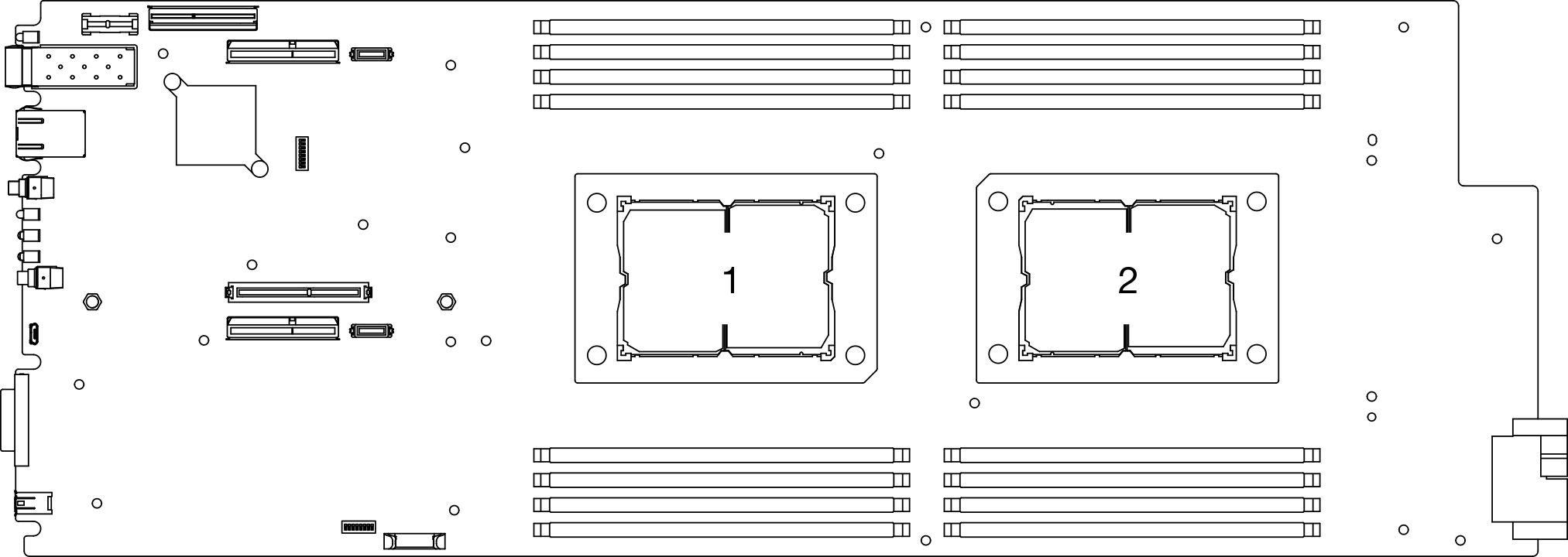
The heat sink, processor, and processor carrier for your system might be different from those shown in the illustrations.
PHMs are keyed for the socket where they can be installed and for their orientation in the socket.
See Lenovo ServerProven website for a list of processors supported for your server. All processors on the system board must have the same speed, number of cores, and frequency.
Before you install a new PHM or replacement processor, update your system firmware to the latest level. See Update the firmware.
For ThinkSystem DA240 Enclosure and ThinkSystem SD630 V2 Compute Node, T-shaped heat sink is only applicable to processor socket 2.
Installing an additional PHM can change the memory requirements for your system. See Install a memory module for a list of processor-to-memory relationships.
The following types of heat sinks are applicable to SD630 V2:
Processors with TDP (thermal design power) ≤ 165W:
113x124x23.5mm heat sink (aluminum fins) is applicable to both processor socket 1 and 2.
Processors with TDP (thermal design power) ≥ 185W:
113x124x23.5mm heat sink (copper fins) is only applicable to processor socket 1.
T-shaped heat sink is only applicable to processor socket 2.
Make sure to install the correct number of fans based on your configuration.
Two fans:
- Processors with TDP (thermal design power) ≤ 165W
Three fans:
- Processors with TDP (thermal design power) ≥ 185W
- Intel(R) Xeon(R) Gold 6334 (165W, 8 core)
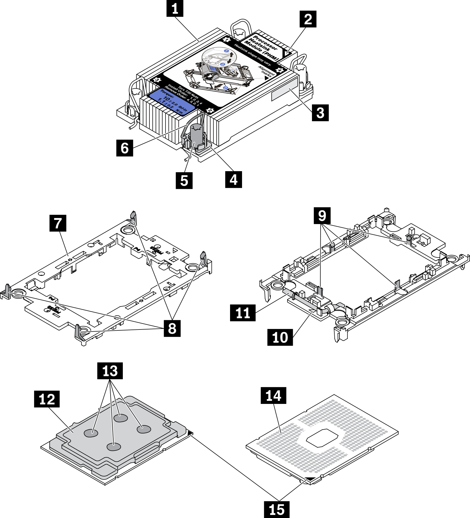
| 1 Heat sink | 9 Clips to secure processor in carrier |
| 2 Heat sink triangular mark | 10 Carrier triangular mark |
| 3 Processor identification label | 11 Processor ejector handle |
| 4 Nut and wire bail retainer | 12 Processor heat spreader |
| 5 Torx T30 nut | 13 Thermal grease |
| 6 Anti-tilt wire bail | 14 Processor contacts |
| 7 Processor carrier | 15 Processor triangular mark |
| 8 Clips to secure carrier to heat sink |
- A video of this procedure is available at YouTube.
Procedure
- Install the processor-heat-sink module into the system board socket.Figure 3. PHM installation
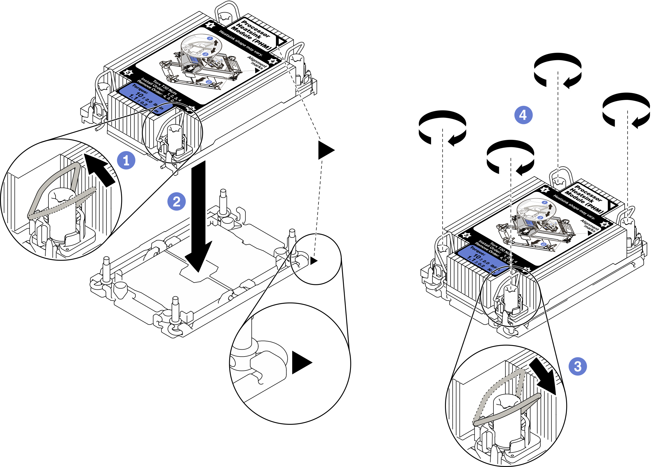
 Rotate the anti-tilt wire bails inward.
 Align the triangular mark and four Torx T30 nuts on the PHM with the triangular mark and threaded posts of the processor socket; then, insert the PHM into the processor socket.
 Rotate the anti-tilt wire bails outward until they engage with the hooks in the socket.
 Fully tighten the Torx T30 nuts in the installation sequence shown on the heat sink label. Tighten the screws until they stop; then, visually inspect to make sure that there is no gap between the screw shoulder beneath the heat sink and the processor socket.NoteFor reference, the torque required to fully tighten or loosen the fasteners is 1.1 newton-meters, 10 inch-pounds.AttentionTo prevent damage to components, make sure that you follow the indicated installation sequence.
- Based on your configuration, follow the corresponding procedures to install the T-shaped heat sink that comes with processor 2.Figure 4. T-shaped heat sink installation
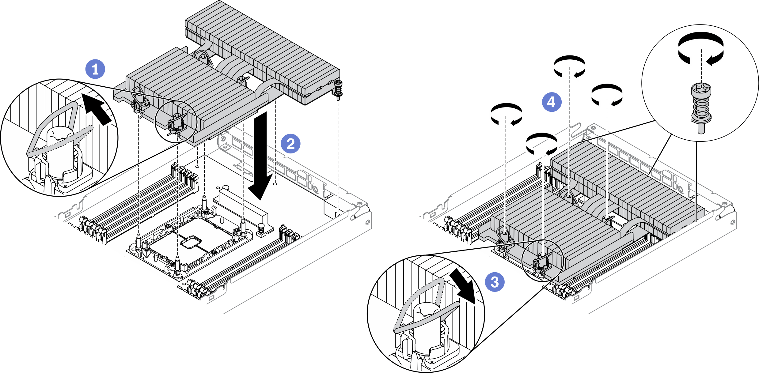
- For the four Torx T30 nuts, rotate the anti-tilt wire bails inward.
- Align the triangular mark and four Torx T30 nuts on the T-shaped heat sink with the triangular mark and threaded posts of the processor socket; then, insert the T-shaped heat sink into the processor socket.
- Rotate the anti-tilt wire bails outward until they engage with the hooks in the socket.
- Fully tighten the four Torx T30 nuts and three captive screws in the installation sequence shown on the T-shaped heat sink label as illustrated below. Then, visually inspect to make sure that there is no gap between the screw shoulder beneath the heat sink and the processor socket.NoteFor reference, the torque required to fully tighten or loosen the fasteners is 1.1 newton-meters, 10 inch-pounds.AttentionTo prevent damage to components, make sure that you follow the indicated installation sequence.
Installation sequence: 1, 2, 3, 4, 5, 6, 7.
Figure 5. Torx T30 nuts and screws numbering on T-shaped heat sink label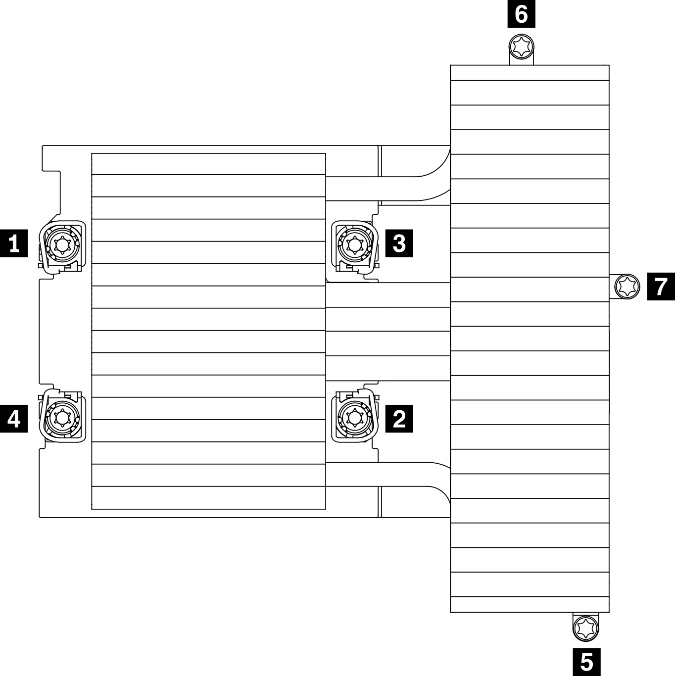
1 2 3 4 Torx T30 nuts 5 6 7 Captive screws
After you finish
- Reinstall the node air baffles (see Install the front air baffle and Install the middle air baffle).
- Reinstall the compute node into the enclosure (see Install a compute node in the enclosure).
Check the power LED on each node to make sure it changes from fast blink to slow blink to indicate the node is ready to be powered on.
Demo video