Install the shielding cables
Use this information to install the shielding cables.
About this task
To identify the gap pad/putty pad location and orientation, see:
Required Tools list in the following section.
Before replacing the gap pad/putty pad, gently clean the interface plate or the hardware surface with an alcohol cleaning pad.
Hold the gap pad/putty pad carefully to avoid deformation. Make sure no screw hole or opening is blocked by the gap pad/putty pad material.
Do not use expired putty pad. Check the expiry date on putty pad package. If the putty pads are expired, acquire new ones to properly replace them.
Required tools
Make sure you have the required tools listed below in hand to properly replace the component.
Compute node water loop carrier
(The water loop carrier in the Service Kit is reusable, it is recommended to keep it at the facility where the server operates for future replacement needs.)
SD665-N V3 Water Loop Gap Pad Kit
SD665-N V3 Miscellaneous Parts Kit
SD665-N V3 Water Loop Putty Pad Kit
SD665-N V3 OSFP Putty Pad Kit
VR 2.5 mm Putty Pad
(Optional, only when there are shielding cables on the defect system board) Shielding cables
Putty pad cannot be reused. Whenever the water loop is removed, putty pads must be replaced with new ones before reinstalling the water loop.
Drive gap pad or putty pad kits according to the drives installed in the tray. See their respective replacement procedures for more information.
Screws and screwdrivers
Prepare the following screwdrivers to ensure you can install and remove corresponding screws properly.Screwdriver Type Screw Type Hex screw (GPU node water loop) 6 mm hex head screwdriver Hex screw (OSFP module conduction plate) 4.5 mm hex head screwdriver Torx T10 head screwdriver Torx T10 screw Torx T20 head screwdriver Torx T20 screw Phillips #1 head screwdriver M3 screw Phillips #2 head screwdriver Phillips #2 screw 3/16" hex head screwdriver M3 screw
Read Installation Guidelines and Safety inspection checklist to ensure that you work safely.
Turn off the corresponding DWC tray that you are going to perform the task on.
Disconnect all external cables from the enclosure.
Use extra force to disconnect QSFP cables if they are connected to the solution.
To avoid damaging the water loop, always use the water loop carrier when removing, installing or folding the water loop.
Procedure
Depending on the model, your solution might look slightly different from the illustration.
- Identify the shielding cables.
Shielding cable 1 Shielding cable 1 (connected with shielding cable 2 by Y cable) 2 Shielding cable 2 (connected with shielding cable 1 by Y cable) 3 Shielding cable 3 4 Shielding cable 4 (attached shielding cage is smaller than shielding cable 3) Figure 1. shielding cable 1/2, 3, and 4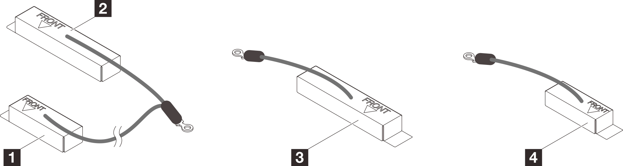
- Place shielding cable 1/2 and shielding cable 3 on top of the screw holes on system board.
- Locate the screw holes for shielding cable 1/2 and shielding cable 3.
1 Screw hole for shielding cable 1/2 2 Screw hole for shielding cable 3 Figure 2. Location of screw holes of shielding cable 1/2 and 3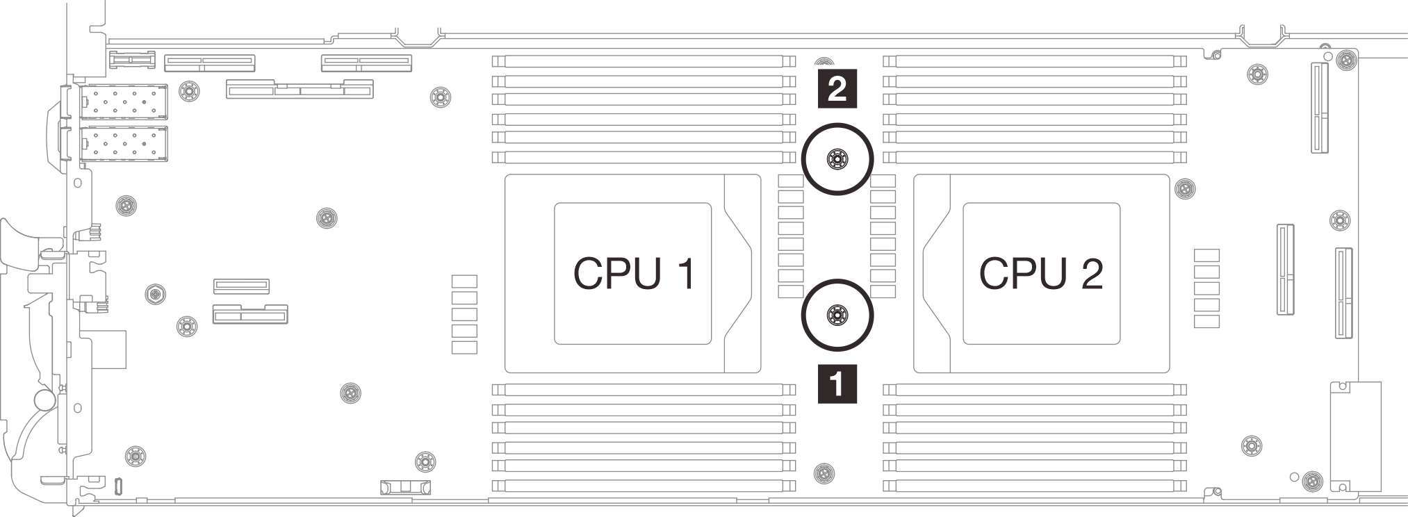
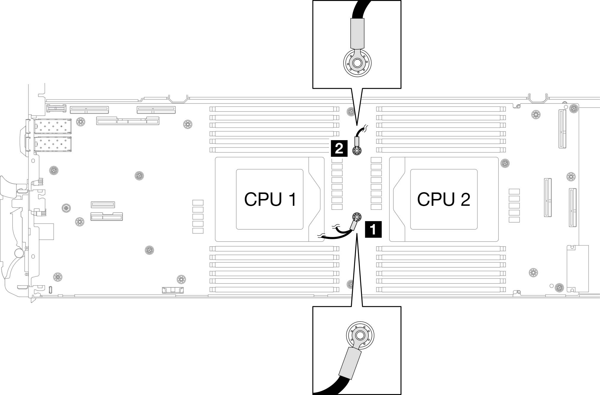
- Align shielding cable 1/2 and shielding cable 3 to the screw holes on system board. Make sure the ring terminals of the cable are placed in the angle shown below.Figure 3. Aligning shielding cable 1/2 and shielding cable 3 with screw holes
- Locate the screw holes for shielding cable 1/2 and shielding cable 3.
- Install shielding cable 1/2 and 3.
 Keep the FRONT marking on the VR conduction plate pointing the front of the tray. Then, place the VR conduction plate on top of the two cable ring terminals.Note
A putty pad is attached to the bottom side of the VR conduction plate. Carefully hold the VR conduction plate to avoid damaging the putty pad.
Figure 4. Aligning VR conduction plate, shielding cables, and system board screw holes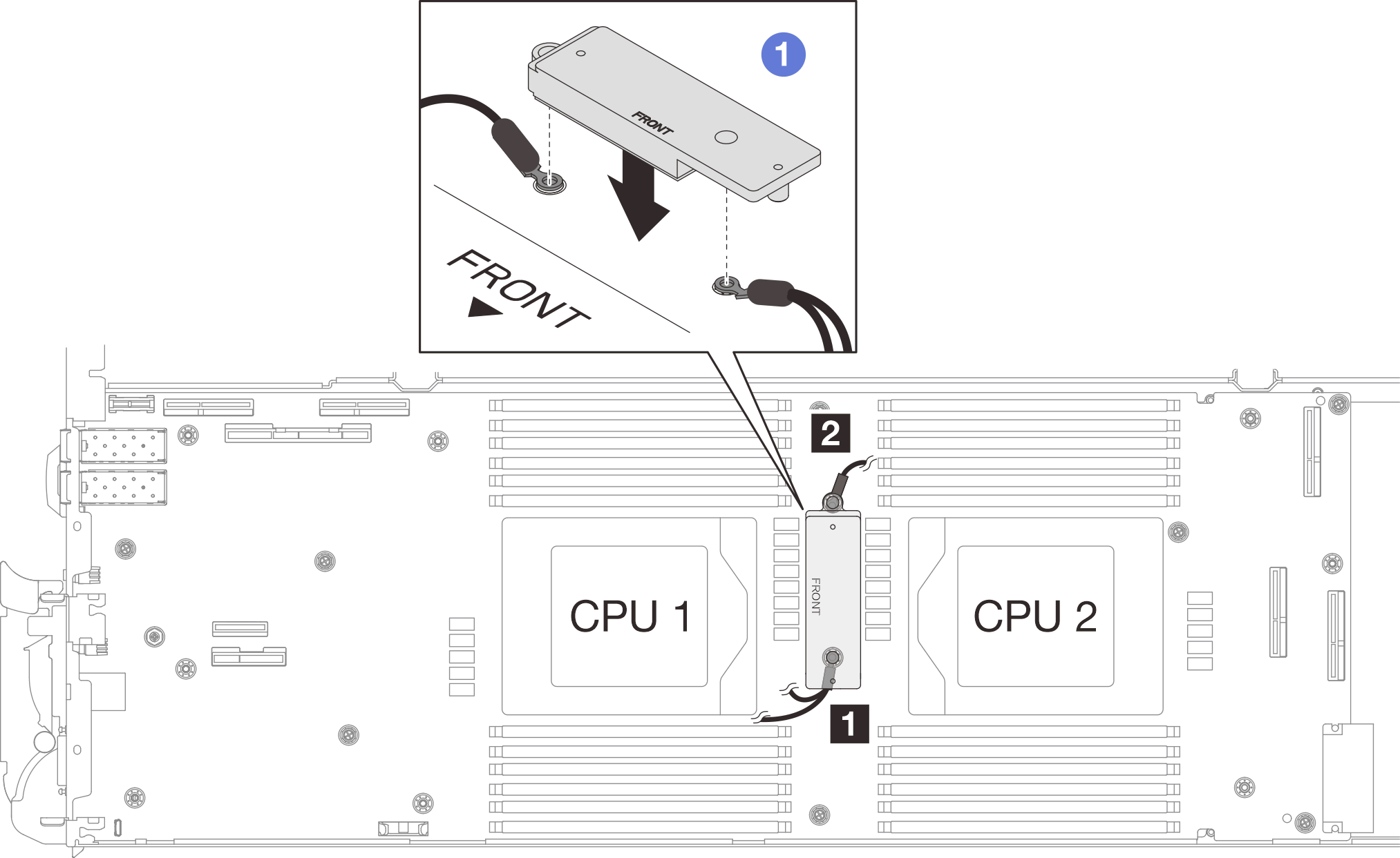
 Slightly press down the VR conduction plate.AttentionThe following items will be secured by screw. Make sure they are aligned and do not block each other.
Screw hole on the system board
The hole on the ring terminal of the shielding cage cable
Screw hole on the VR conduction plate
Figure 5. Pressing on the VR conduction plate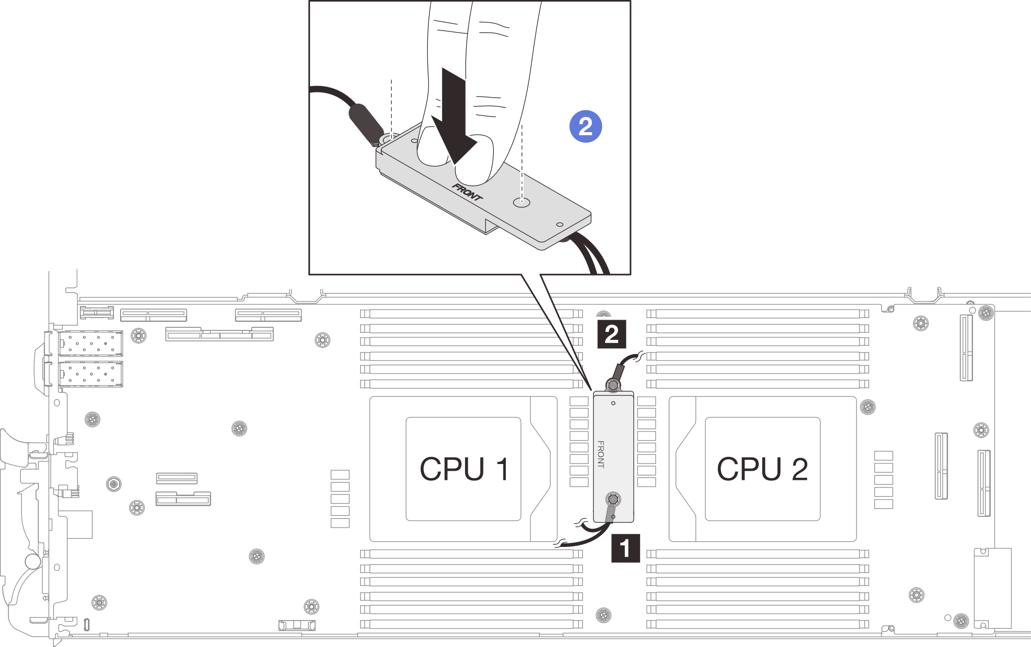
 While pressing down the VR conduction plate, place the screws into the two screw holes on the VR conduction plate. Then, fasten the two screws to secure the cables to the system board. DO NOT fasten the screws until both screws are placed into the VR conduction plate.Figure 6. Installing shielding cable 1/2 and 3
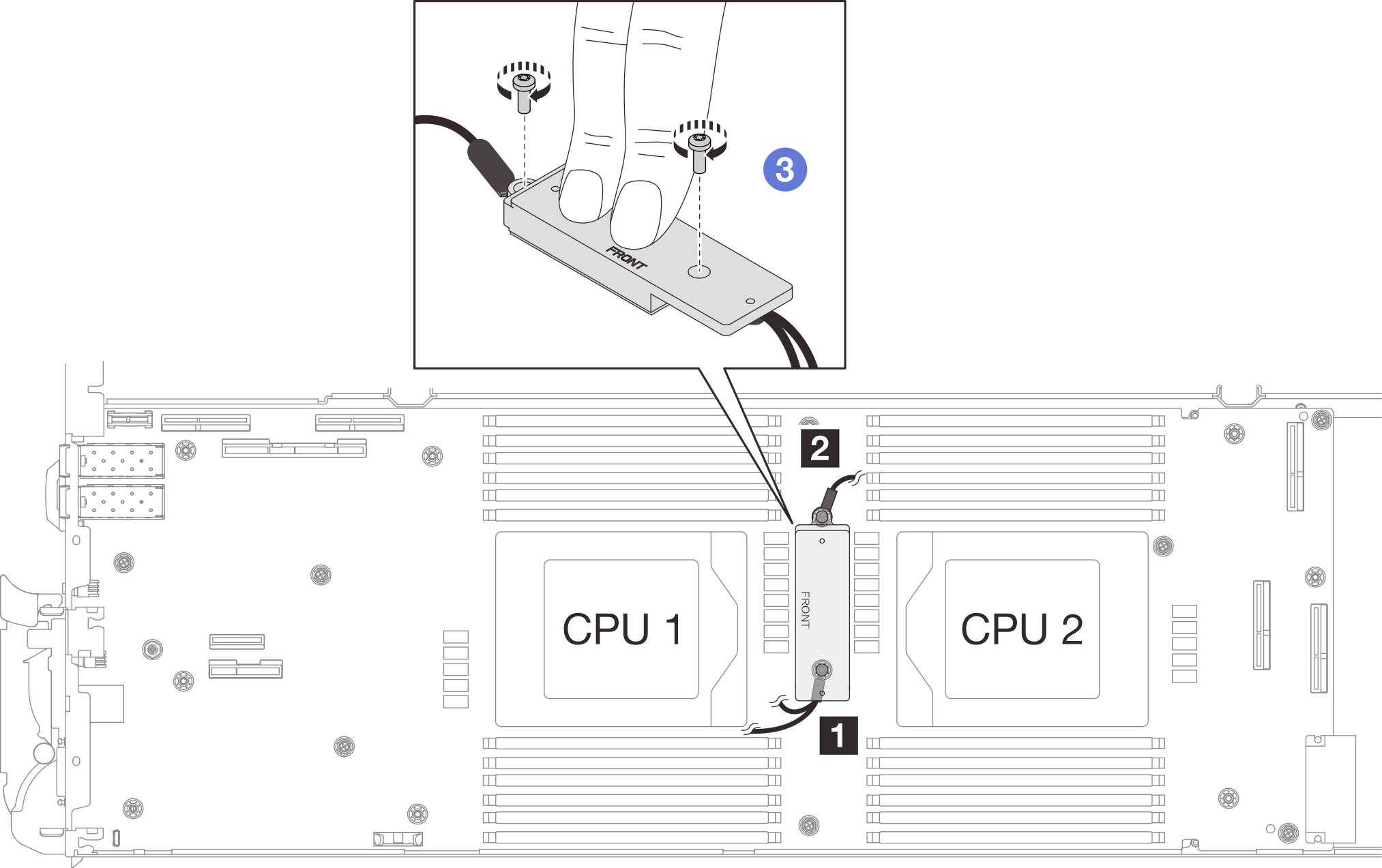
- Locate the screw hole for braided cable 4. Then, align shielding cable 4 to the screw holes on system board as shown below. Make sure the ring terminal of the cable is placed in the angle shown below. Fasten the screw to secure the shielding cable to the system board.
1 Screw hole for shielding cable 4 Figure 7. Location of screw hole of shielding cable 4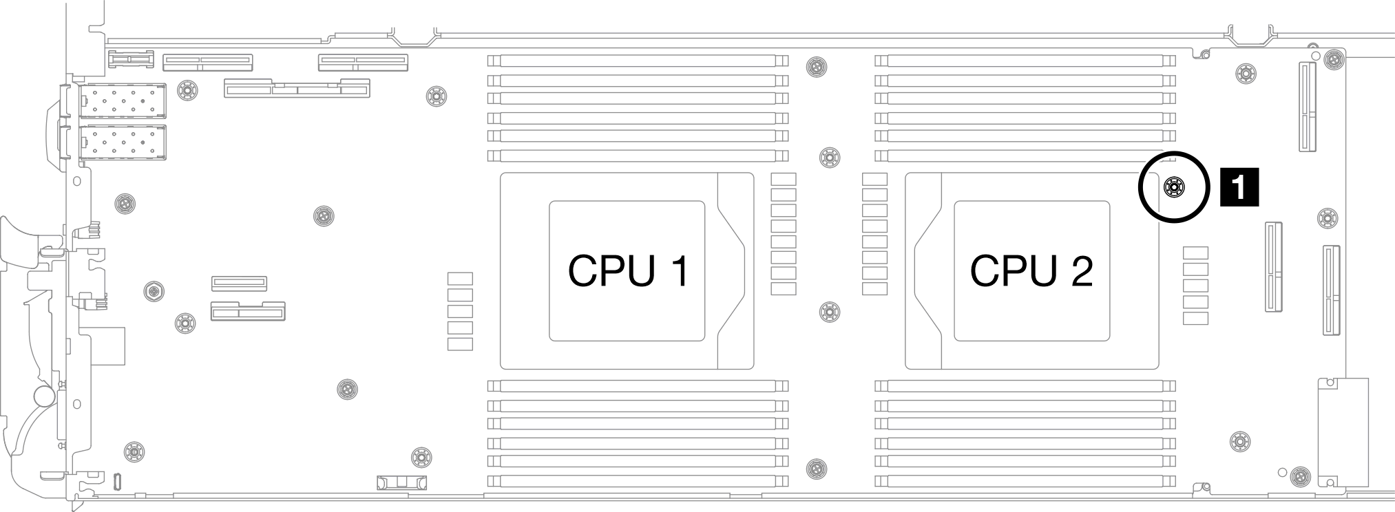 Figure 8. Installing shielding cable 4
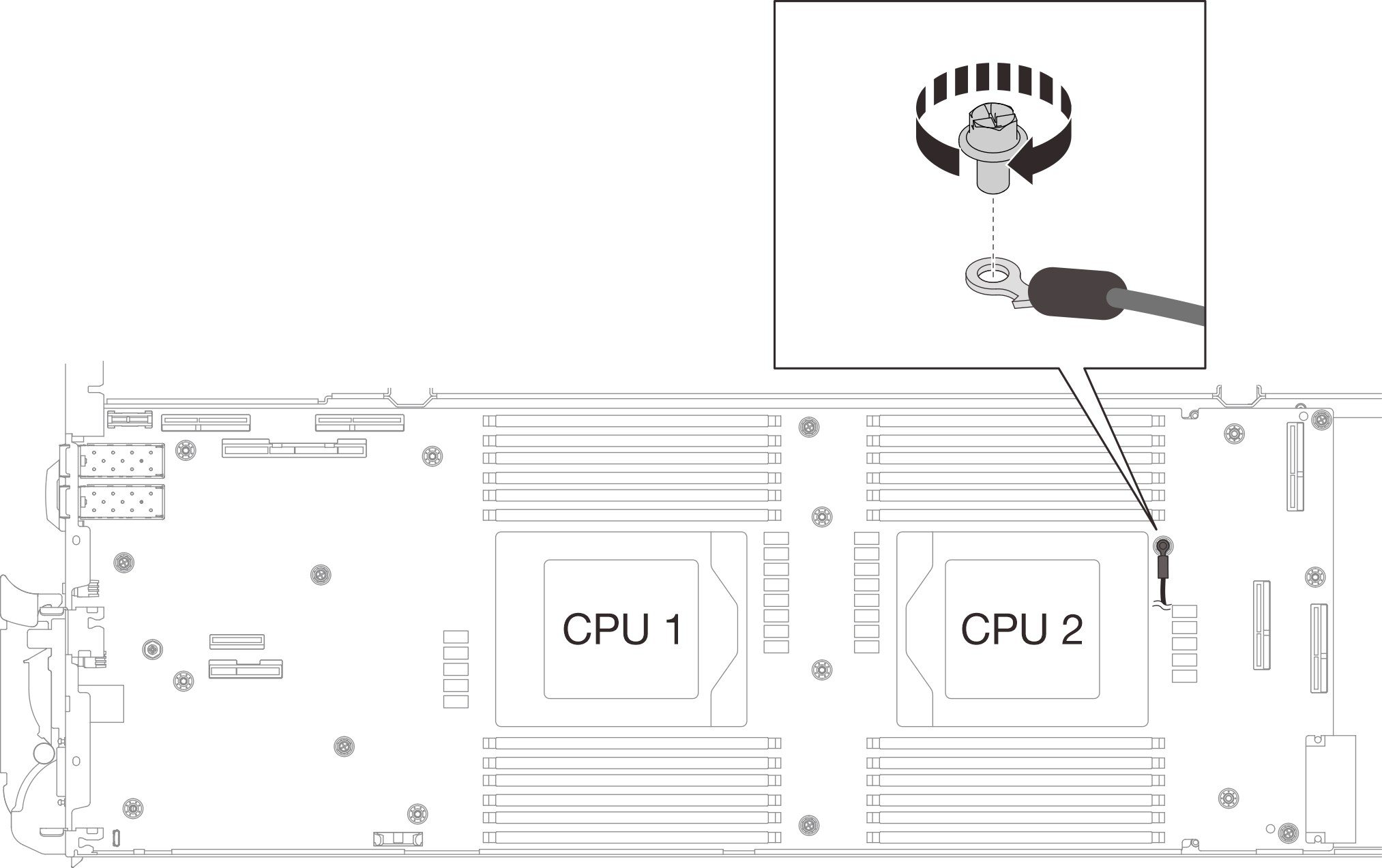
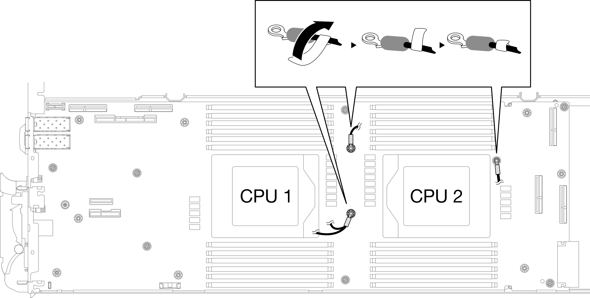
- There are labels attached to shielding cable 1, 3, and 4. Roll the label around the cable all the way through to prevent label interfering with system connectors and water loop.Figure 9. Rolling label around the shielding cable
- From the inside of the shielding cages, hold the tab and peel off the adhesive tapes. Complete the step for all four shielding cages.
1 Adhesive tape tab Figure 10. Peeling off the adhesive tape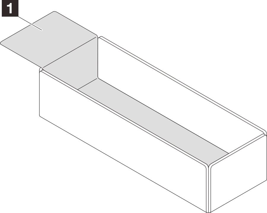
- Cover the inductors on system board with shielding cages.
- Follow the inductors and shielding cable mapping table below.
Table 1. Shielding cage and inductors mapping table Shielding cage (attached to the shielding cable) Inductor on the system board to be covered by the shielding cage Shielding cable 1 (connected with shielding cable 2 by Y cable) A Shielding cable 2 (connected with shielding cable 1 by Y cable) B Shielding cable 3 C Shielding cable 4 (attached shielding cage is smaller than shielding cable 3) D Figure 11. shielding cable 1/2, 3, and 4Figure 12. Inductors locations on the system board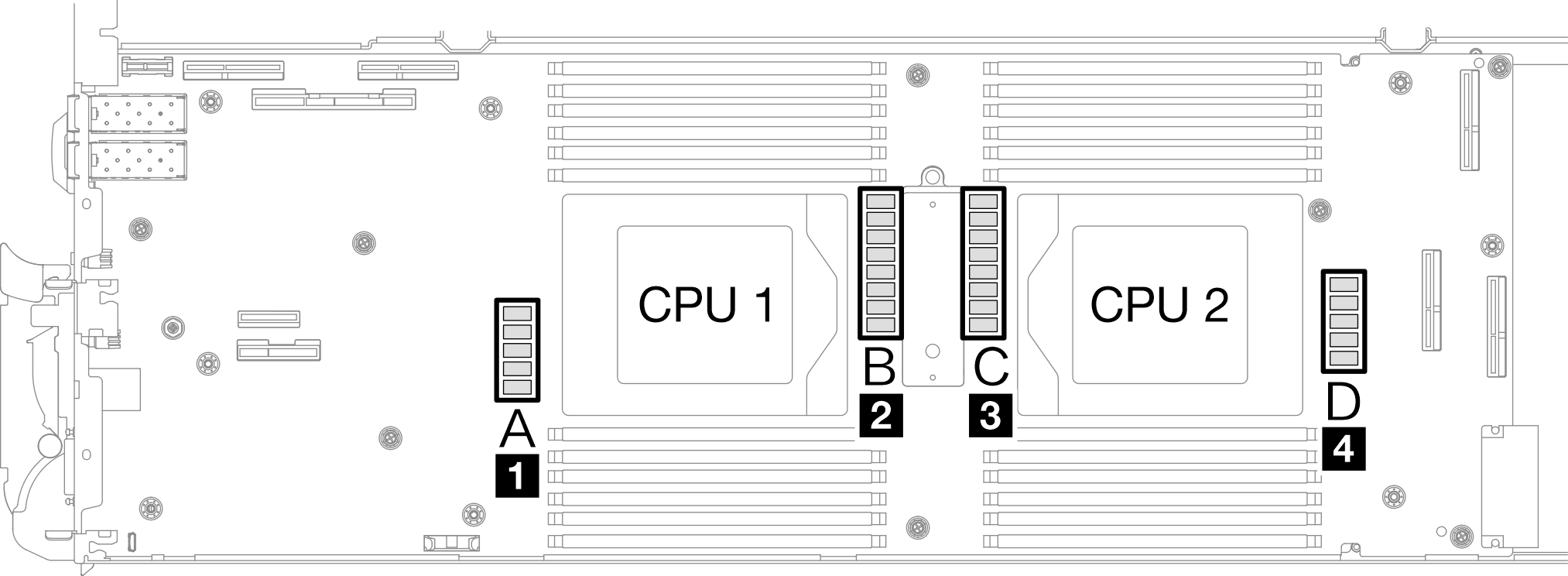
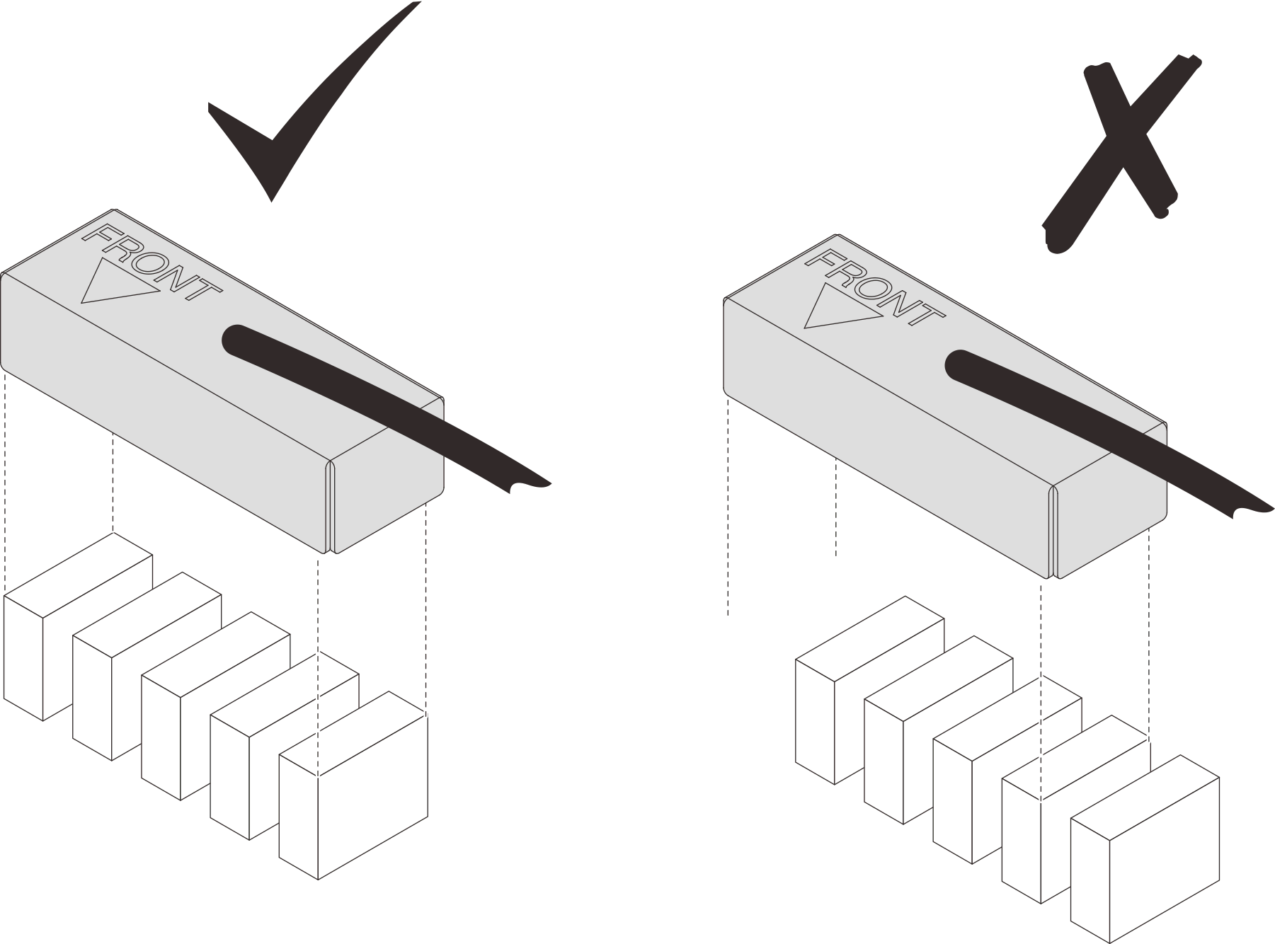
- Before covering the inductors with shielding cages, make sure the FRONT marking on the shielding cage points at the front of the tray.AttentionAfter covering the inductors with shielding cages,
DO NOT remove the shielding cages from the system board to avoid system board damages. Figure 13. Front marking on the cage pointing at the front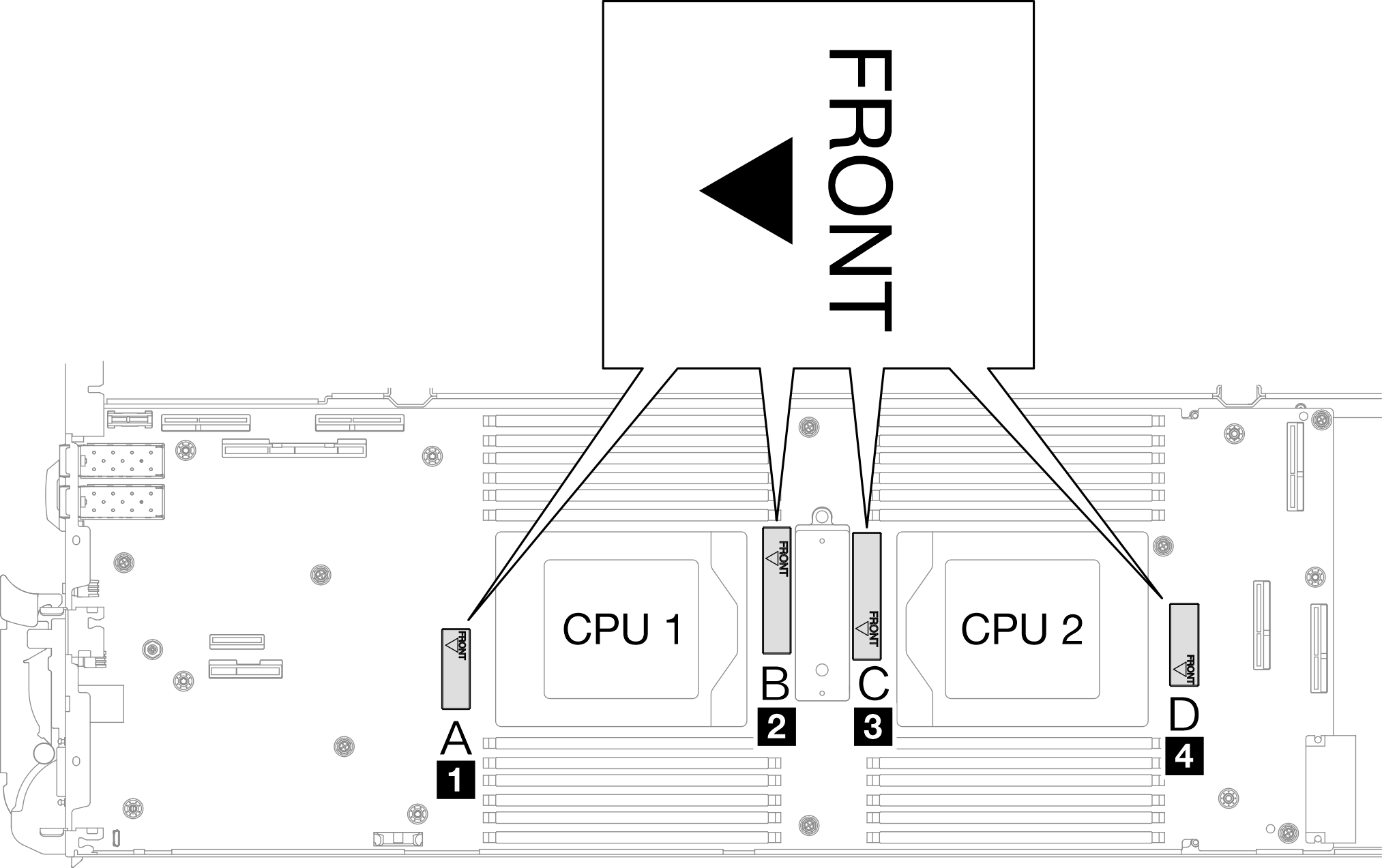
- Attach the inside of the shielding cage to the inductor attaching point. In the graphic below, the dotted lines specify the inductor attaching points for the inside of the cage. The inductor attaching point is where the inside of the cage and the inductors attach to each other seamlessly without any gap.Note
Shielding cage 1 and 4: one attaching point
Shielding cage 2 and 3: two attaching points
For the non-attaching-point side of cage 1 and 4, balance the gap between the inside of the cage and inductors.
1 Shielding cage 2 Inductor 3 Inductor attaching point Figure 14. Inductor attaching points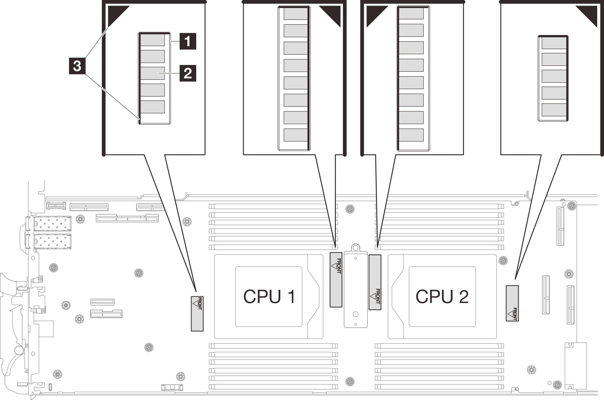
- Keep the shielding cage attached to the inductor attaching point and make sure the inductors are completely covered; then, lower the cage into the system board.Figure 15. Covering the inductors with the shielding cage
- Follow the inductors and shielding cable mapping table below.
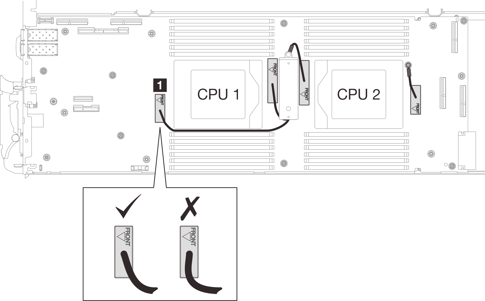
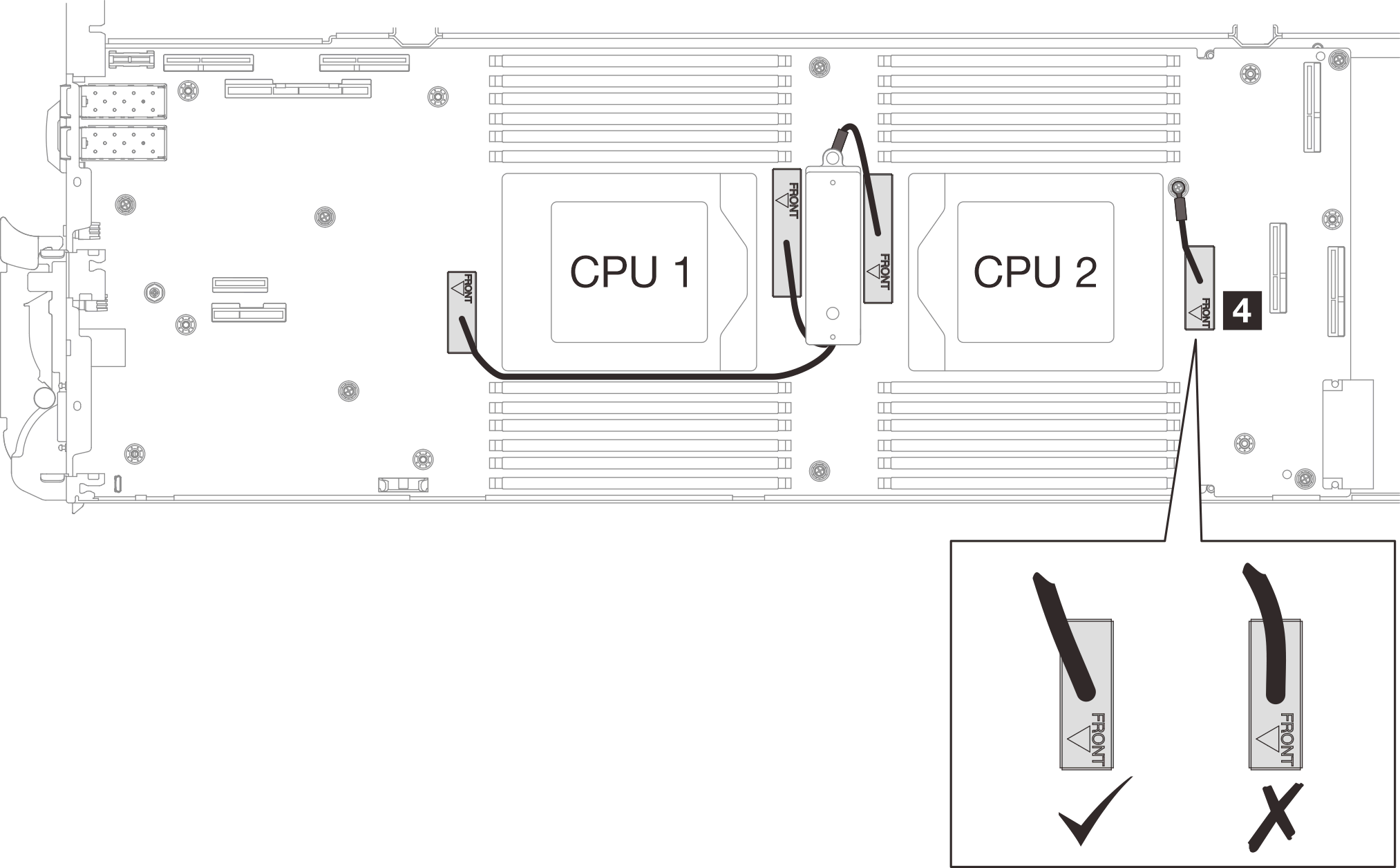
- Route the shielding cable 1 between CPU 1 socket and the DIMM slots. Make sure all shielding cable are cleared from CPU sockets, DIMM slots, and other system board connectors.Note
Make sure the FRONT marking on the cage points at the front of the tray.
Shielding cable 1 Shielding cable 1 (connected with shielding cable 2 by Y cable) 2 Shielding cable 2 (connected with shielding cable 1 by Y cable) 3 Shielding cable 3 4 Shielding cable 4 (attached shielding cage is smaller than shielding cable 3) Figure 16. Cable routing for shielding cages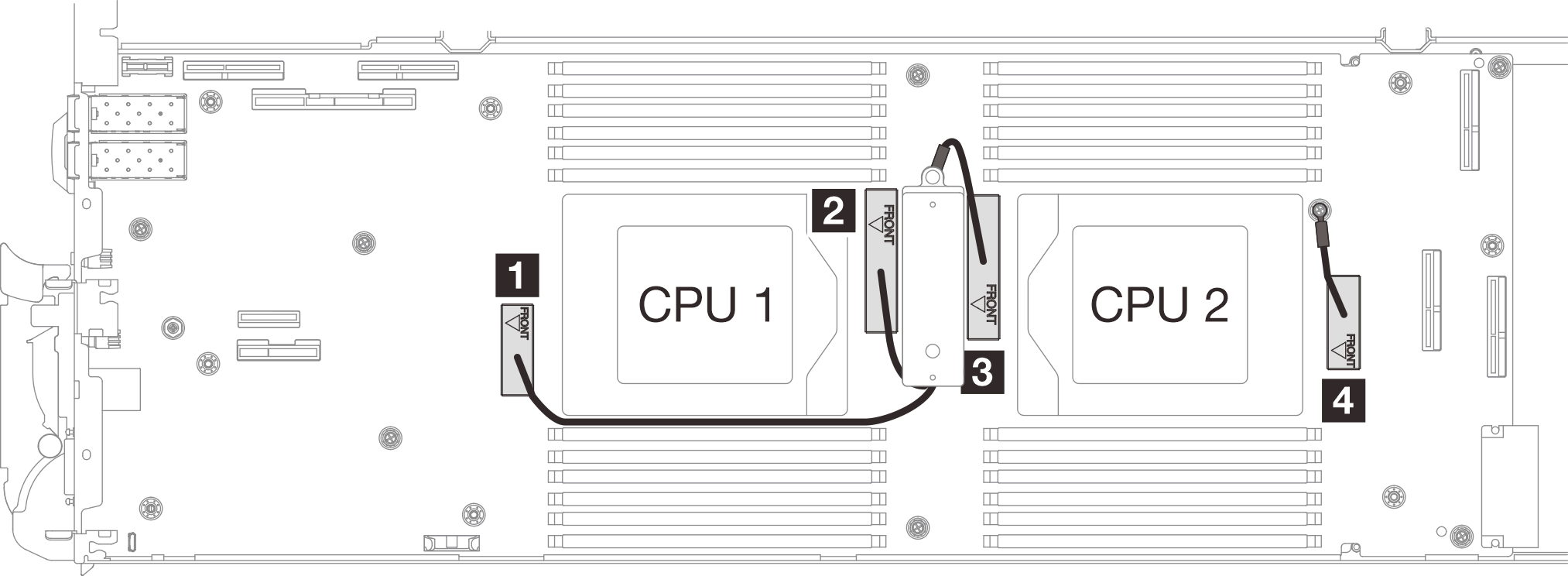
The shielding cable 1 should be angled toward CPU 1.
The shielding cable 4 cable should be angled toward the CPU 2.
Proceed to complete installing the system board. See Install the system board.