Remove the system board
Use this information to remove the system board.
About this task
Required tools
Make sure you have the required tools listed below in hand to properly replace the component.
Compute node water loop carrier
(The water loop carrier in the Service Kit is reusable, it is recommended to keep it at the facility where the server operates for future replacement needs.)
SD665-N V3 Water Loop Gap Pad Kit
SD665-N V3 Miscellaneous Parts Kit
SD665-N V3 Water Loop Putty Pad Kit
SD665-N V3 OSFP Putty Pad Kit
VR 2.5 mm Putty Pad
(Optional, only when there are shielding cables on the defect system board) Shielding cables
Putty pad cannot be reused. Whenever the water loop is removed, putty pads must be replaced with new ones before reinstalling the water loop.
Drive gap pad or putty pad kits according to the drives installed in the tray. See their respective replacement procedures for more information.
Screws and screwdrivers
Prepare the following screwdrivers to ensure you can install and remove corresponding screws properly.Screwdriver Type Screw Type Hex screw (GPU node water loop) 6 mm hex head screwdriver Hex screw (OSFP module conduction plate) 4.5 mm hex head screwdriver Torx T10 head screwdriver Torx T10 screw Torx T20 head screwdriver Torx T20 screw Phillips #1 head screwdriver M3 screw Phillips #2 head screwdriver Phillips #2 screw 3/16" hex head screwdriver M3 screw
Read Installation Guidelines and Safety inspection checklist to ensure that you work safely.
Turn off the corresponding DWC tray that you are going to perform the task on.
Disconnect all external cables from the enclosure.
Use extra force to disconnect QSFP cables if they are connected to the solution.
To avoid damaging the water loop, always use the water loop carrier when removing, installing or folding the water loop.
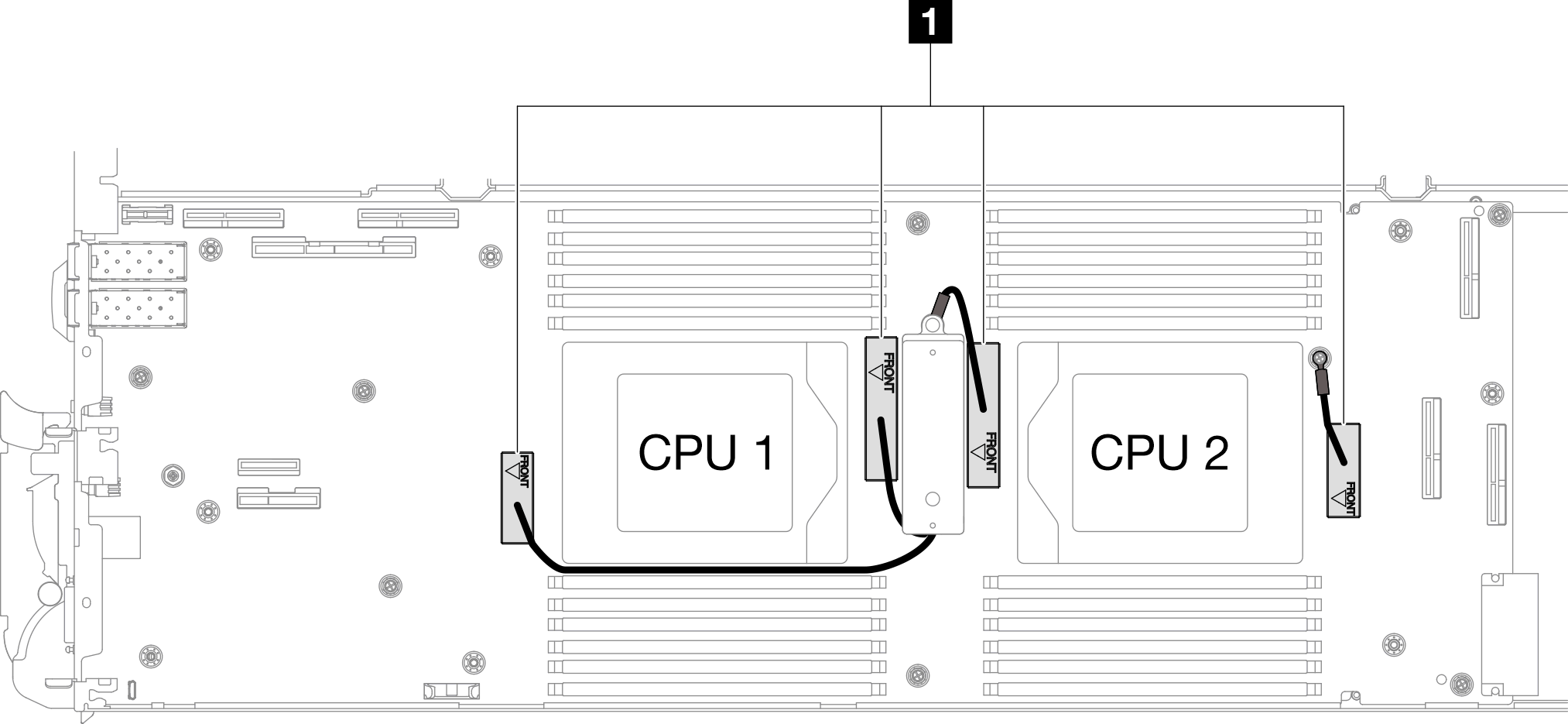
If there are shielding cables on the system board, when removing the system board, do not remove the shielding cables (1) from the system board.
Procedure
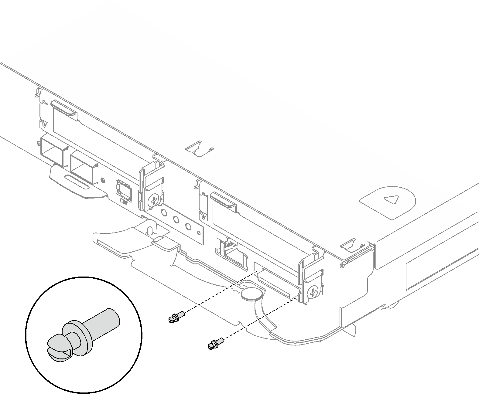
- Remove the two KVM screws from the front of the node with a torque screwdriver set to the proper torque.NoteFor reference, the torque required for the screws to fully tightened/removed is 1.3+/-0.5 lb-in, 0.15+/- 0.05 N-M.Figure 1. KVM screws removal
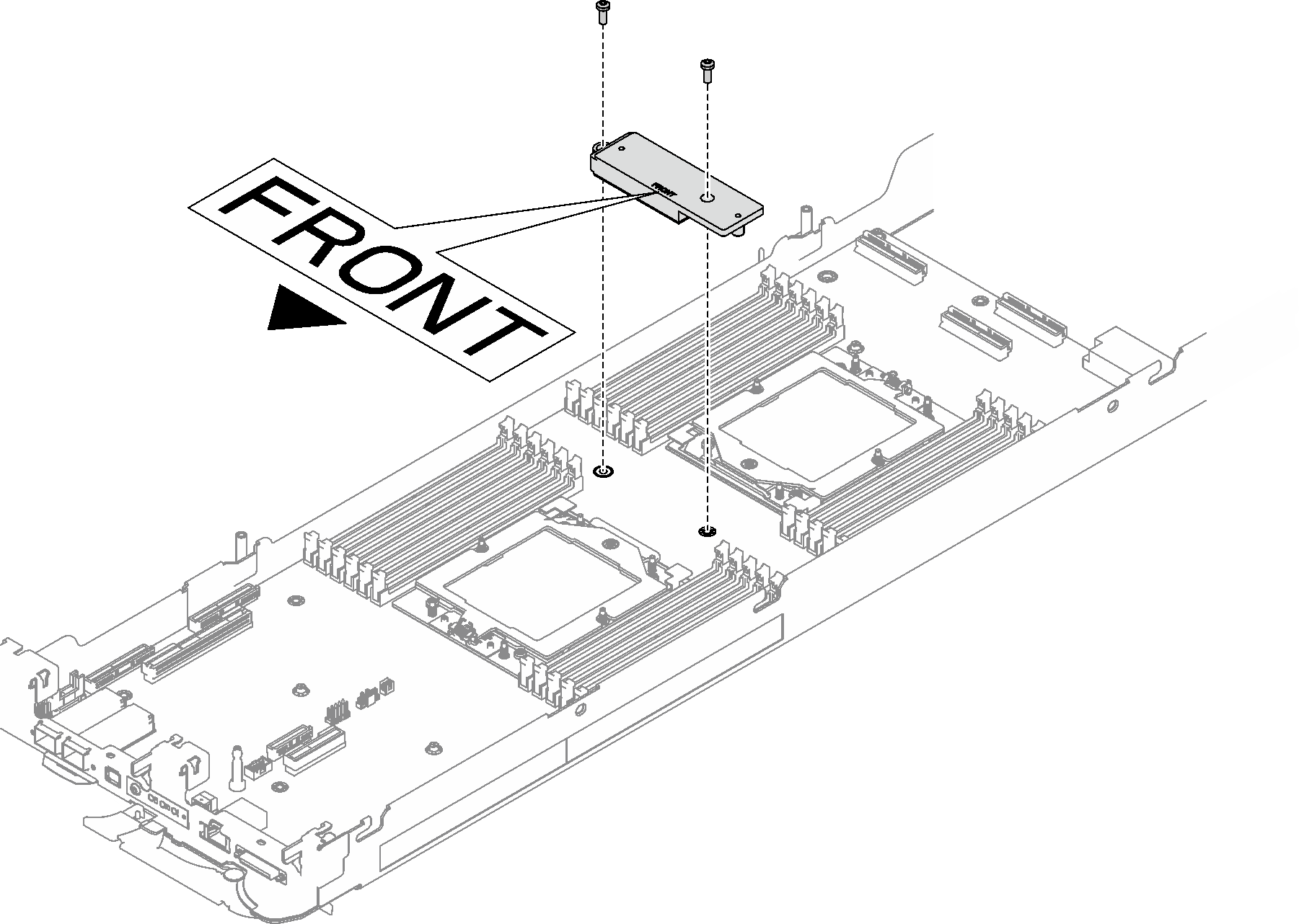
- Remove the two M3 screws to remove the VR conduction plate out of the system board.NoteKeep the VR conduction plate for future use.Figure 2. VR conduction plate removal
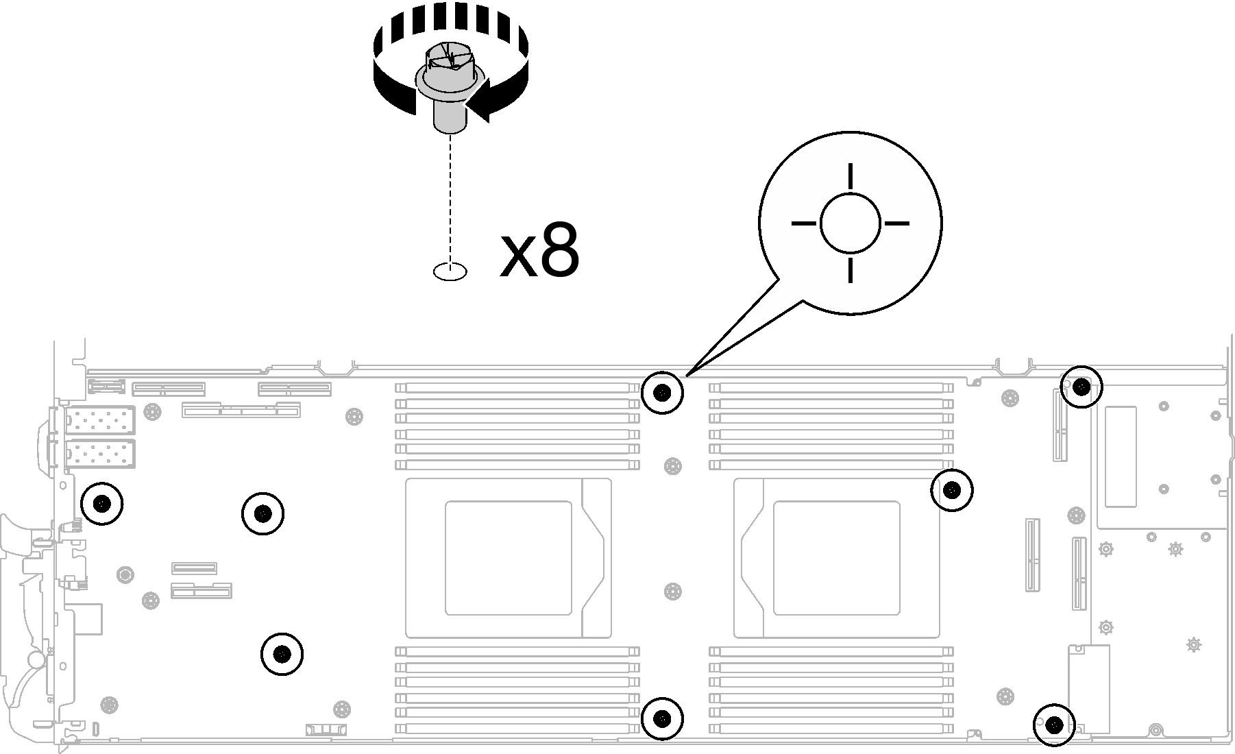
- Remove eight M3 screws per node on the system board with a 3/16" hex head screwdriver set to the proper torque.NoteFor reference, the torque required for the screws to be fully tightened/removed is 5.0+/- 0.5 lbf-in, 0.55+/- 0.05 N-M.Figure 3. System board screws removal
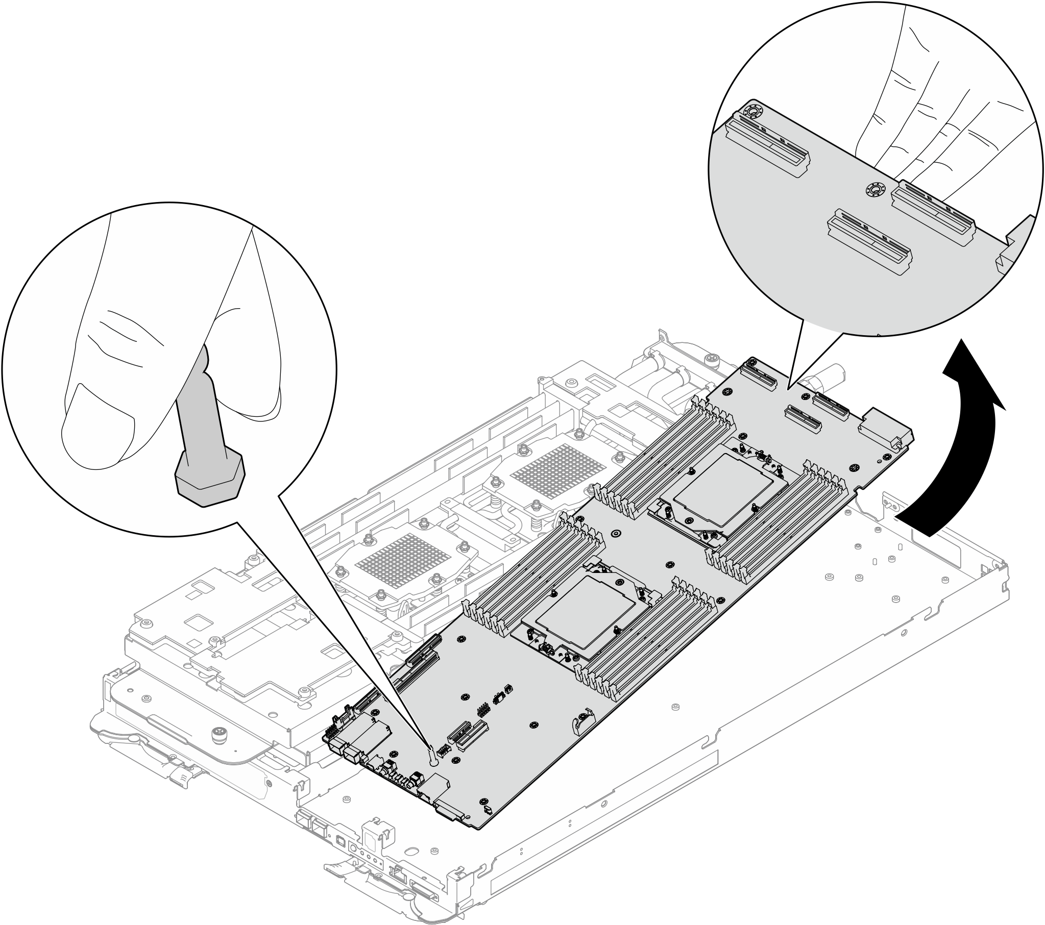
- Carefully hold the guide pin and tilt the system board at an angle; then, gently slide and lift the system board backwards to remove the system board from the node.NoteAvoid touching the connectors on the system board. Be careful not to damage any surrounding components inside the node.Figure 4. System board removal
If you are instructed to return the component or optional device, follow all packaging instructions, and use any packaging materials for shipping that are supplied to you.
For installing a new system board, see Install the system board.
For transferring the system board to another tray, see Transfer the system board.
Take a dust cover from the processor socket assembly on the new system board and orient it correctly above the processor socket assembly on the removed system board.
Gently press down the dust cover legs to the processor socket assembly, pressing on the edges to avoid damage to the socket pins. You might hear a click on the dust cover is securely attached.
Make sure that the dust cover is securely attached to the processor socket assembly.
Remove the guide pin out of the system board.
Figure 5. Guide pin removal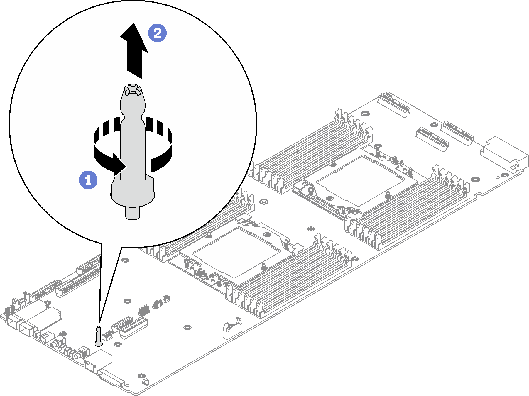
Recycle the unit in compliance with local regulations.
Demo video