8 x 2.5-inch front drive bays
Use this section to understand the backplane cable routing for server model with eight 2.5-inch front drives.
To connect cables for a 7mm drive backplane, refer to 7mm drive backplane.
To connect power cables for a backplane for standard 2.5-inch or 3.5-inch drives, refer to 2.5-inch/3.5-inch drive backplane (power).
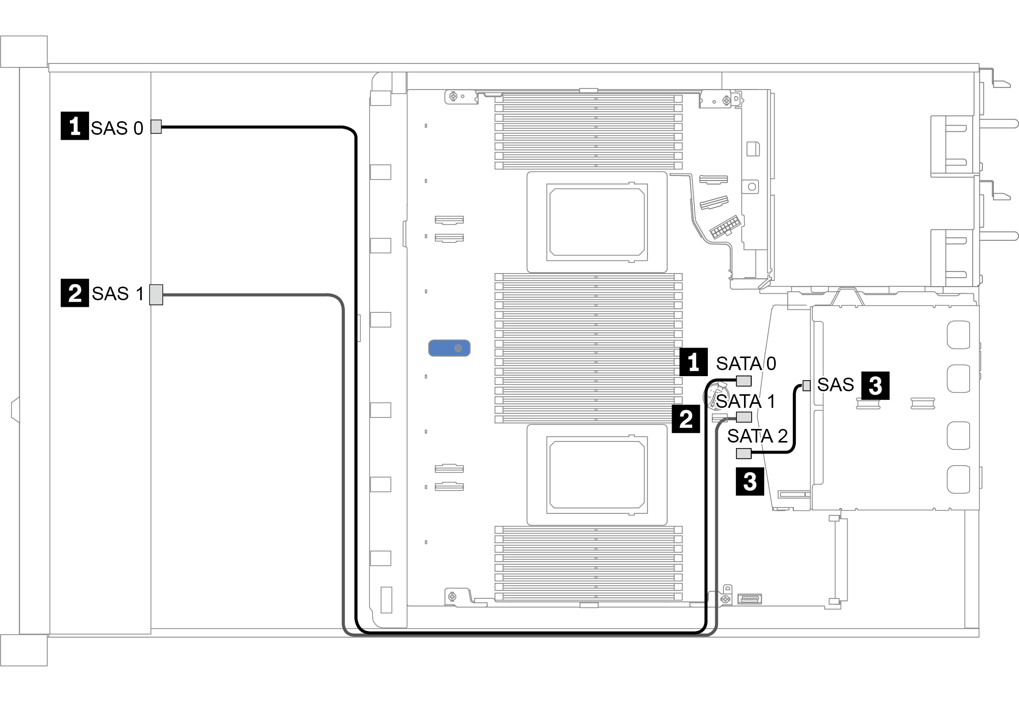
Cable routing for onboard configuration
The following table shows the mapping relationship between backplane connectors and system board connectors for onboard configuration.
| Backplanes | From | To |
|---|---|---|
| Front BP (SAS) | SAS 0 | SATA 0 |
| SAS 1 | SATA 1 | |
| Rear BP (if any) | SAS | SATA 2 |
The following figure illustrates the cable routing for the onboard configuration of 8 x 2.5-inch front SAS/SATA drive bays with a rear 2 x 2.5-inch SAS/SATA drive cage. Connections between connectors: 1 ↔ 1, 2 ↔ 2, 3 ↔ 3, ... n ↔ n.
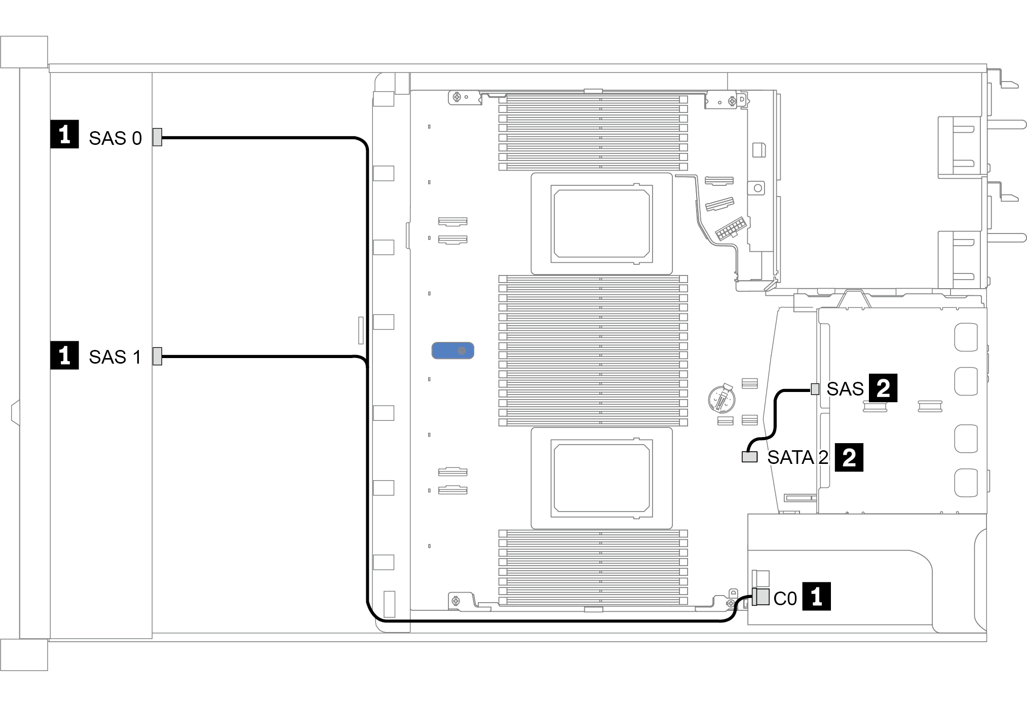
Cable routing with an SFF HBA/RAID adapter
The following table shows the mapping relationship between backplane connectors and system board/adapter connectors when an 8i SFF HBA/RAID adapter (Gen 3 or Gen 4) is installed.
| Backplanes | From | To |
|---|---|---|
| Front BP (SAS) | SAS 0 | C0 |
| SAS 1 | Gen 3: C1; Gen 4: C0 | |
| Rear BP (if any) | SAS | SATA 2 |
The following figure illustrates the cable routing for the configuration of 8 x 2.5-inch front SAS/SATA drive bays with a 8i SFF RAID adapter (Gen 4) and a rear 2 x 2.5-inch SAS/SATA drive cage. Connections between connectors: 1 ↔ 1, 2 ↔ 2, 3 ↔ 3, ... n ↔ n.
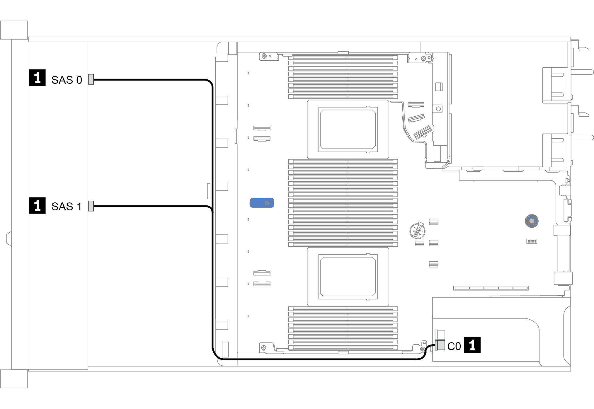
Cable routing with an SFF RAID adapter (tri-mode)
The following table shows the mapping relationship between backplane connectors and adapter connectors when a Gen 4 8i SFF RAID adapter (tri-mode) is installed.
| Backplane | From | To |
|---|---|---|
| Front BP (SAS) | SAS 0, SAS 1 | C0 |
For the server model with eight front 2.5-inch drives, the 10 x 2.5'' AnyBay backplane is used to support the tri-mode configuration.
If a tri-mode RAID adapter is used, only U.3 front drives are supported, and U.2 front drives are not supported.
The following figure illustrates the cable routing for the configuration of 8 x 2.5-inch front U.3 drive bays with a Gen 4 8i SFF RAID adapter (tri-mode). Connections between connectors: 1 ↔ 1, 2 ↔ 2, 3 ↔ 3, ... n ↔ n.
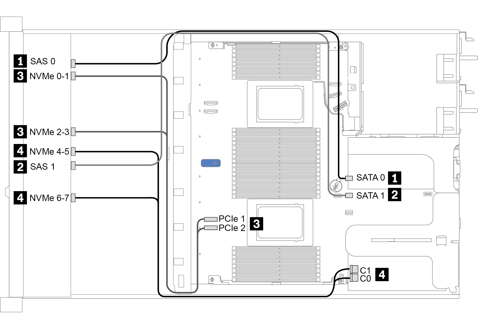
Cable routing with a re-timer card for one processor
The following table shows the mapping relationship between backplane connectors and a re-timer card for one processor.
| Backplane | From | To |
|---|---|---|
| Front BP (SAS) | SAS 0 | SATA 0 |
| SAS 1 | SATA 1 | |
| Front BP (NVMe) | NVMe 0–1, NVMe 2–3 | PCIe 1, PCIe 2 |
| NVMe 4–5, NVMe 6–7 | C0, C1 |
For the server model with eight front 2.5-inch NVMe drives, the 10 x 2.5'' AnyBay backplane is used.
If you take the front view of the chassis, when the re-timer card is installed in PCIe slot 1, the cable is routed on the right side as figure 4 illustrates; when PCIe slot 1 is occupied, install the re-timer card to PCIe slot 2, note that the cable should be routed on the left side.
The following figure illustrates the cable routing for the configuration of 8 x 2.5-inch front NVMe drive bays with a re-timer card. Connections between connectors: 1 ↔ 1, 2 ↔ 2, 3 ↔ 3, ... n ↔ n.
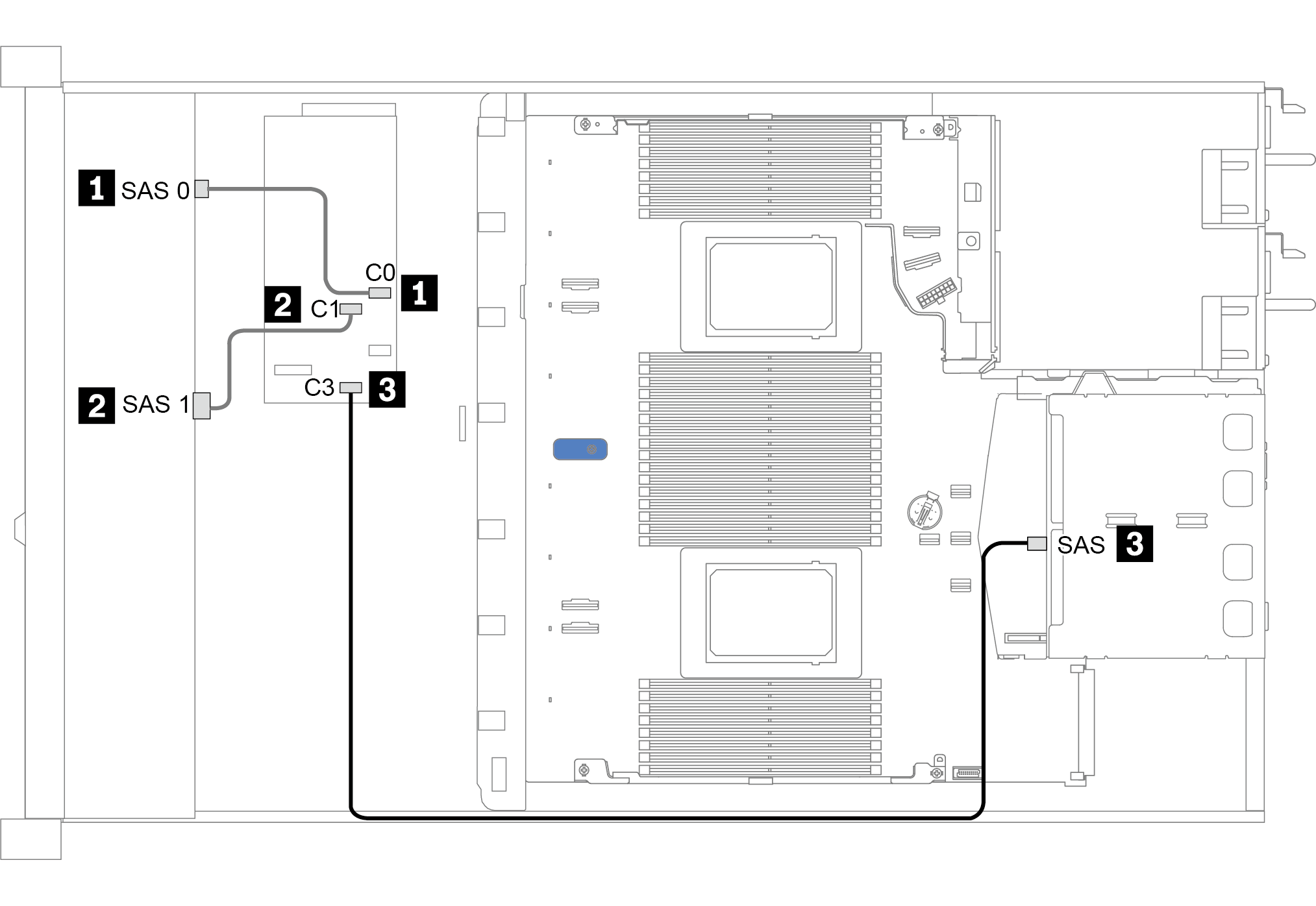
Cable routing with a CFF HBA/RAID adapter
The following table shows the mapping relationship between backplane connectors and adapter connectors when a 16i CFF HBA/RAID adapter is installed.
| Backplanes | From | To |
|---|---|---|
| Front BP (SAS) | SAS 0 | C0 |
| SAS 1 | C1 | |
| Rear BP (if any) | SAS | C3 |
The following figure illustrates the cable routing for the configuration of 8 x 2.5-inch front SAS/SATA drive bays with a 16i CFF RAID adapter and a rear 2 x 2.5-inch SAS/SATA drive cage. Connections between connectors: 1 ↔ 1, 2 ↔ 2, 3 ↔ 3, ... n ↔ n.