Remove the manifold (in-rack system)
Use this information to remove the manifold in an in-rack direct water cooling system.
About this task
This task must be operated by trained technicians that are certified by Lenovo Service. Do not attempt to remove or install the part without proper training and qualification.
The coolant might cause irritation to the skin and eyes. Avoid direct contact with the coolant.


Read Installation Guidelines and Safety inspection checklist to ensure that you work safely.
Power off the server and peripheral devices and disconnect the power cords and all external cables. See Power off the server.
Prevent exposure to static electricity, which might lead to system halt and loss of data, by keeping static-sensitive components in their static-protective packages until installation, and handling these devices with an electrostatic-discharge wrist strap or other grounding systems.
Ensure proper handling procedures are followed when working with any chemically treated coolant used in the rack cooling system. Ensure that material safety data sheets (MSDS) and safety information are provided by the coolant chemical treatment supplier and that proper personal protective equipment (PPE) is available as recommended by the coolant chemical treatment supplier. Protective gloves and eyewear may be recommended as a precaution.
This task requires two or more people.
Procedure
- Close both ball valves.Figure 1. Closing ball valves
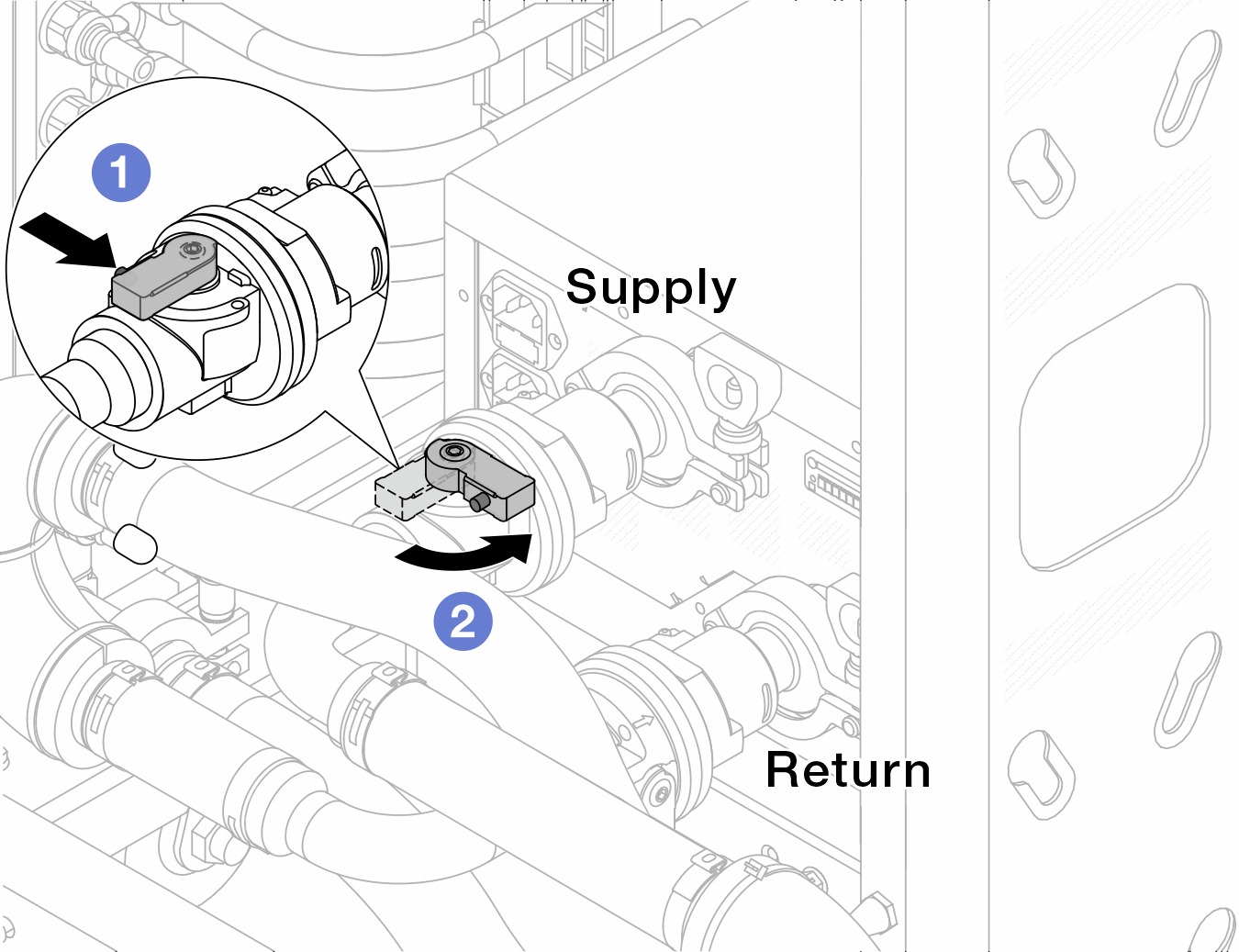
 Press the button on the ball valve switch.
 Rotate the switch to close the valves as illustrated above.
- Remove the quick connect plugs to separate the DWCM hoses from the manifold.Figure 2. Quick connect plug removal
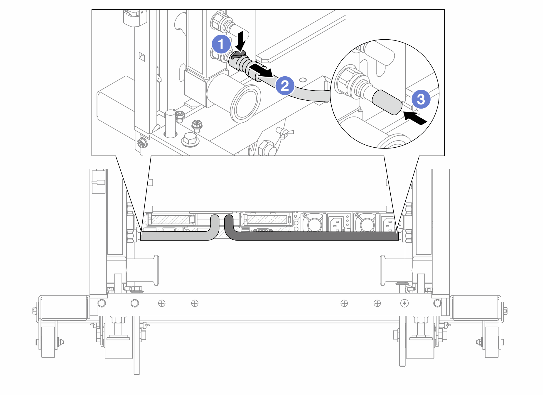
- Press the latch down to unlock the hose.
- Pull the hose off.
 Re-install the rubber quick connect plug covers to the ports on the manifold.
- Disengage the connection set from ball valves.NoteDisengage the return side first, then disengage the supply side.Figure 3. Removing the connection set
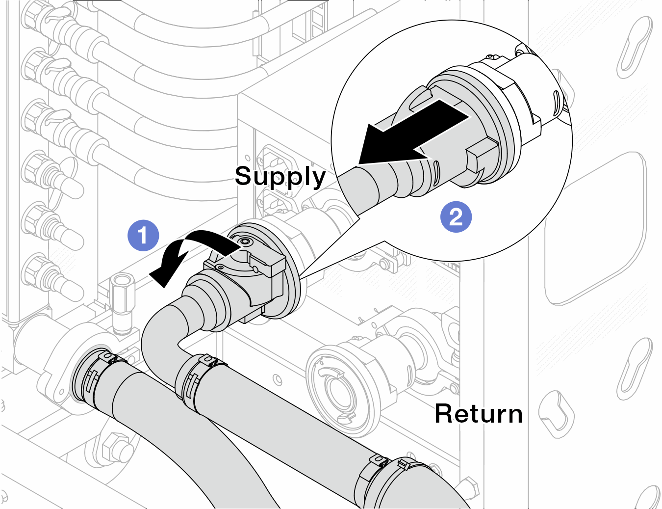
- Rotate the ball valve to the left.
- Pull the connection set off from ball valve.
- Remove the return manifold with the connection set attached.Figure 4. Removing the manifold
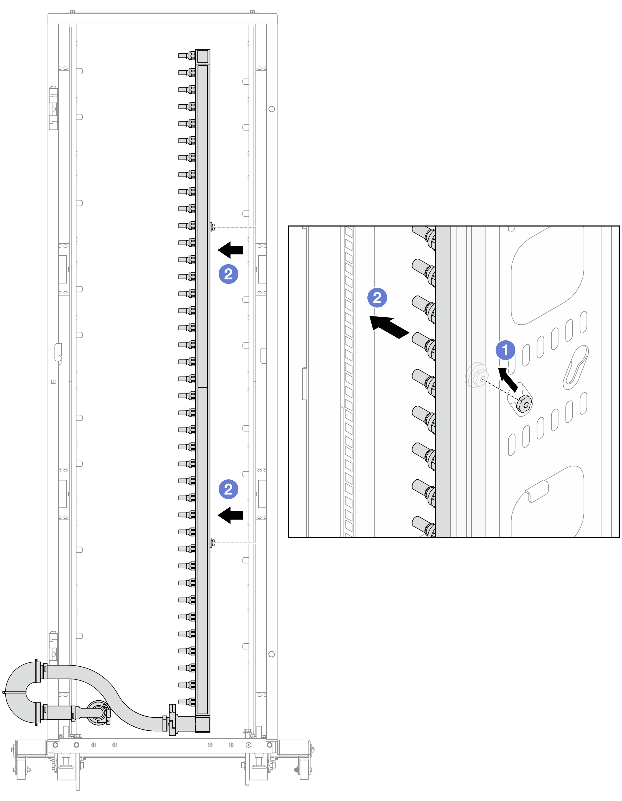
- Hold the manifold with both hands, and lift it upward to relocate the spools from the small openings to large ones on the rack cabinet.
- Remove the manifold with the connection set attached.
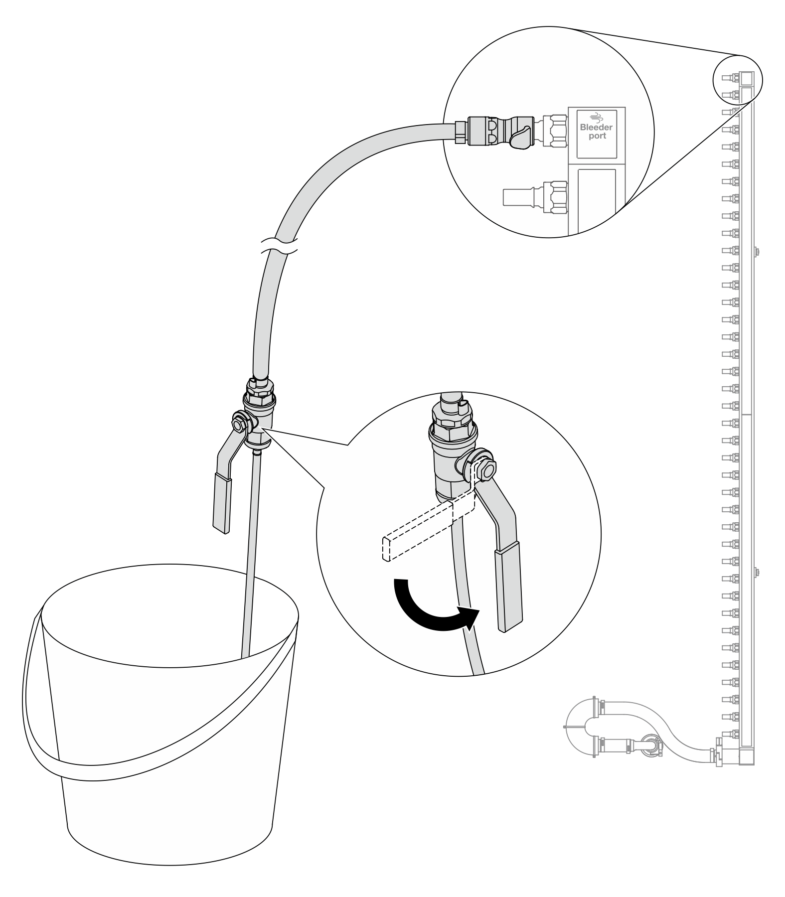
- Install the bleeder kit to the manifold supply side.NoteThis step drains the coolant with the help of a pressure difference inside and outside the supply manifold.Figure 5. Installing the bleeder kit to the supply side
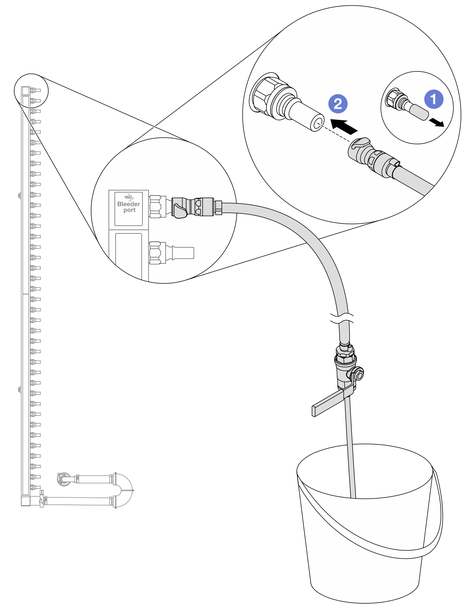
- Remove the rubber quick connect plug covers from the ports on the manifold.
- Plug the bleeder kit to the manifold.
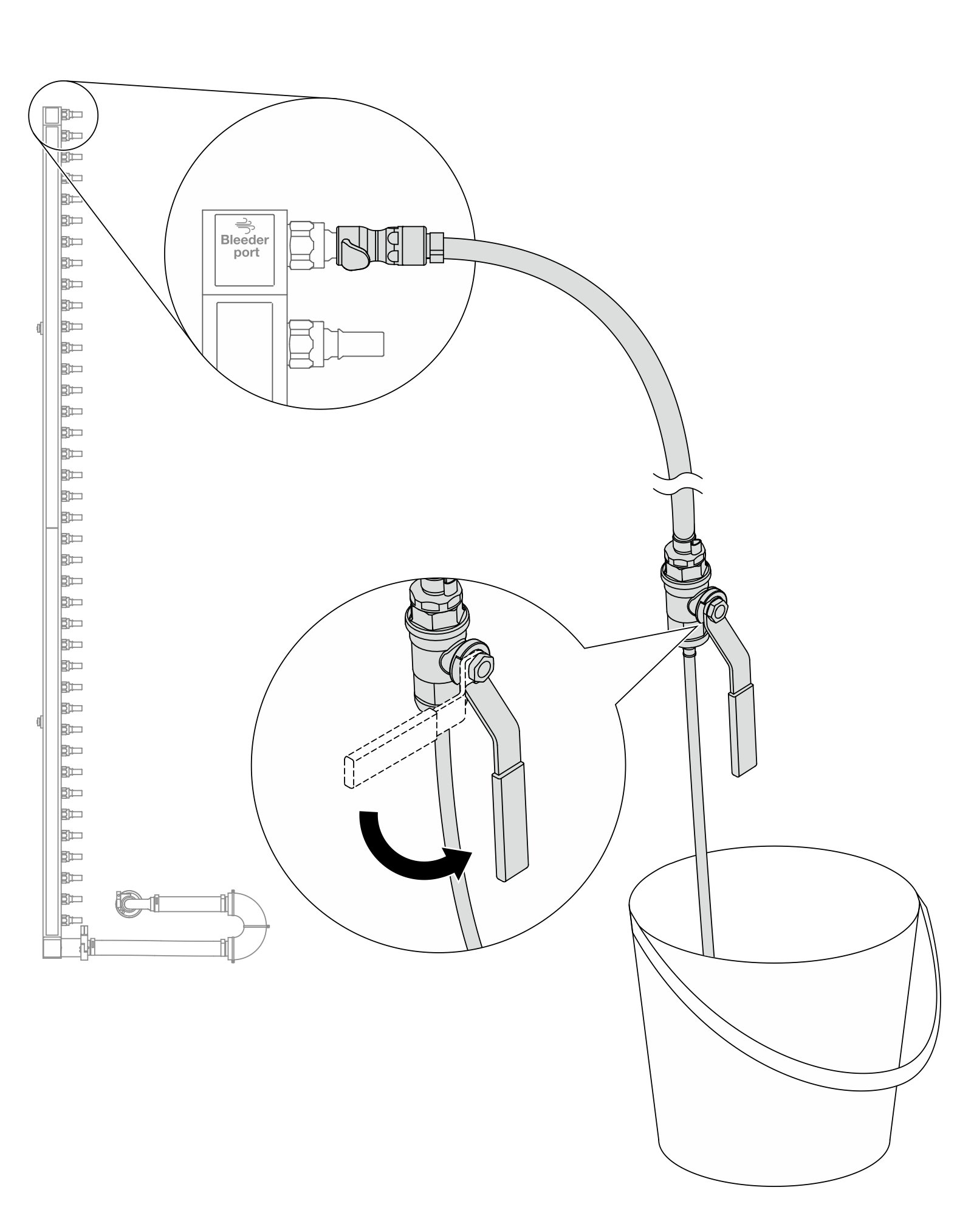
- Slowly open the bleeder valve to allow a steady stream of coolant to drain. Close the bleeder valve once coolant stops flowing.Figure 6. Opening the bleeder valve
- Install the bleeder kit to the manifold return side.NoteThis step drains the coolant with the help of a pressure difference inside and outside the return manifold.Figure 7. Installing the bleeder kit to the return side
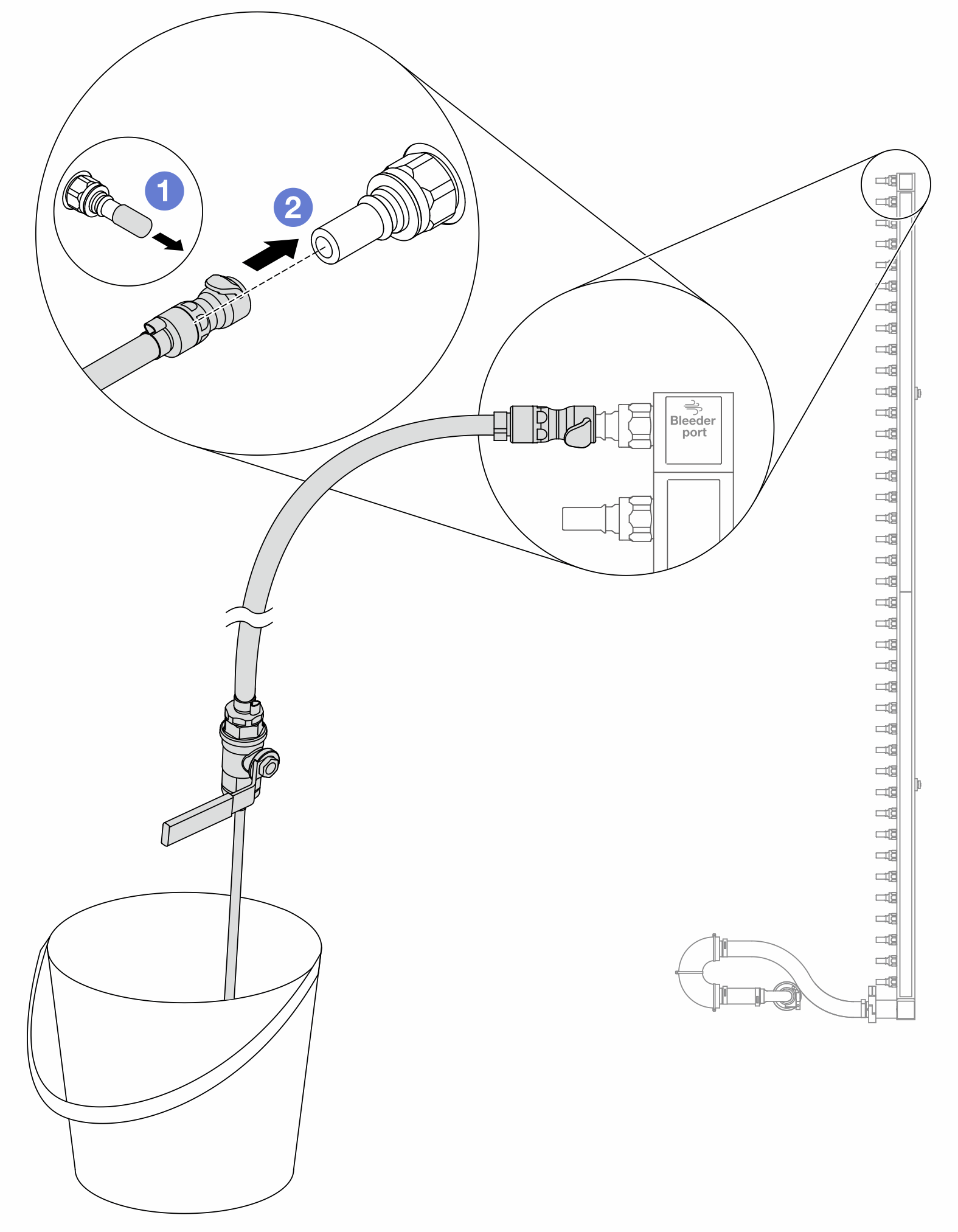
- Remove the rubber quick connect plug covers from the ports on the manifold.
- Plug the bleeder kit to the manifold.
- Slowly open the bleeder valve to allow a steady stream of coolant to drain. Close the bleeder valve once coolant stops flowing.Figure 8. Opening the bleeder valve
- Separate the return manifold from the connection set in a dry and clean work area, and keep a bucket and absorbent cloths around to collect any coolant that may drain out.Figure 9. Separating the manifold from the connection set
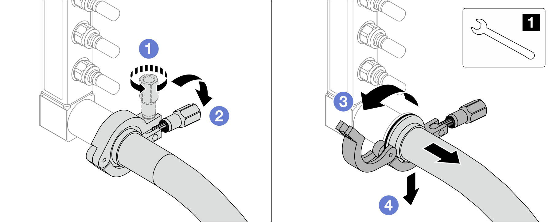
1 17 mm wrench - Loosen the screw that locks the ferrule.
- Put the screw down.
- Open the clamp.
 Remove the ferrule and connection set from the manifold.
If you are instructed to return the component or optional device, follow all packaging instructions, and use any packaging materials for shipping that are supplied to you.
Demo video