Remove the Lenovo Neptune(TM) Processor Direct Water Cooling Module

Follow the instructions in this section to remove the Direct Water Cooling Module (DWCM).

Important

This task must be operated by trained technicians that are certified by Lenovo Service. Do not attempt to remove or install the part without proper training and qualification.

About this task

Safety information for leakage detection sensor module cable
S011
sharp edge
CAUTION
Sharp edges, corners, or joints nearby.
Attention
  • Read Installation Guidelines and Safety inspection checklist to ensure that you work safely.

  • Power off the server and peripheral devices and disconnect the power cords and all external cables. See Power off the server.

  • Prevent exposure to static electricity, which might lead to system halt and loss of data, by keeping static-sensitive components in their static-protective packages until installation, and handling these devices with an electrostatic-discharge wrist strap or other grounding systems.

Prepare the following screwdrivers to ensure you can install and remove the corresponding screws properly.
Torque screwdriver type listScrew Type
Torx T30 head screwdriverTorx T30 screw

Procedure

  1. To remove the quick connect plugs from the manifolds, see Remove the manifold (in-rack system) or Remove the manifold (in-row system).
  2. To remove the server from the rack, see Remove the server from the rack.
  3. Remove the top cover. See Remove the top cover.
  4. Disconnect the leakage detection sensor module cable of the DWCM from the connector on the system board assembly. See Direct water cooling module.
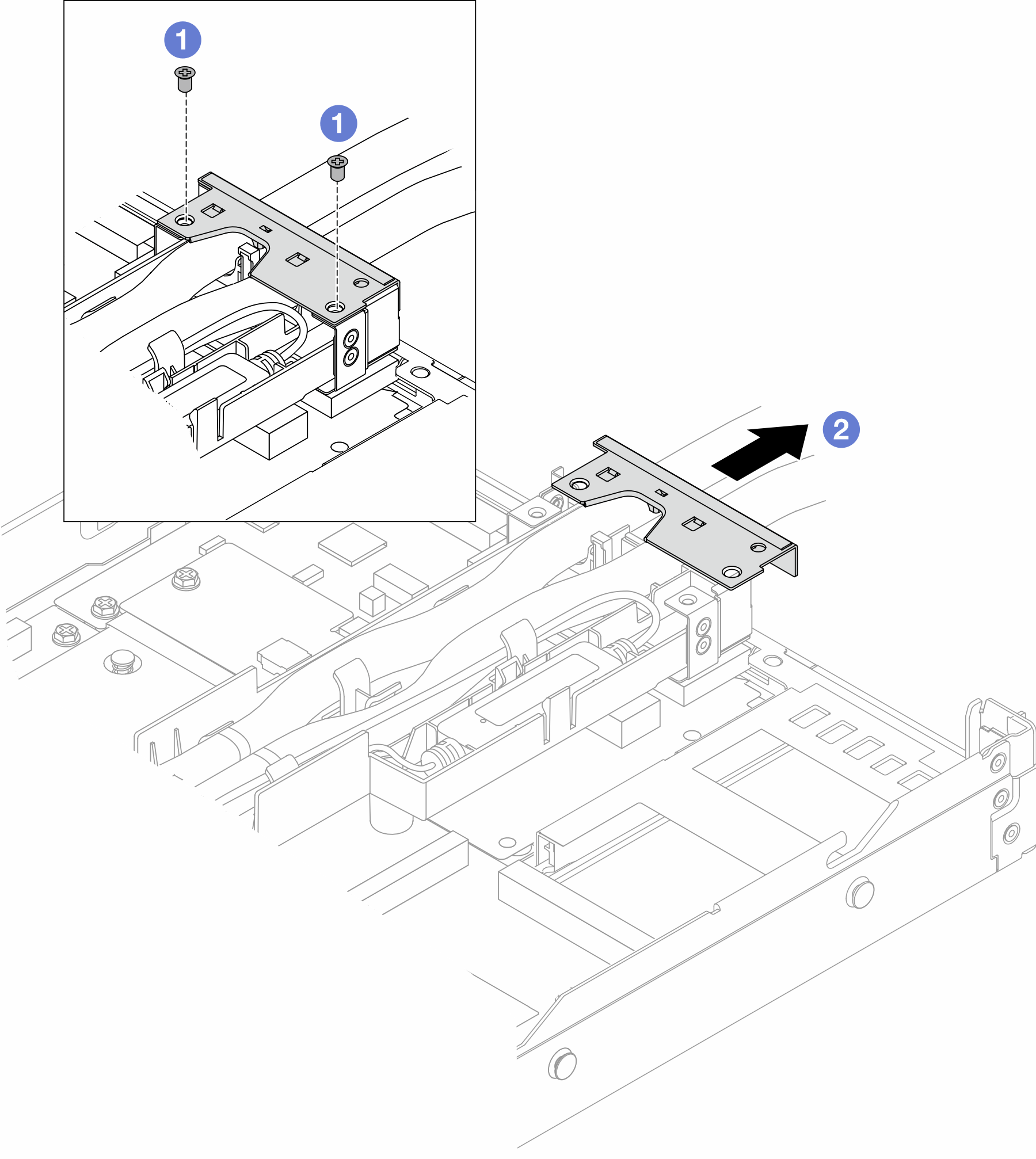
  5. Remove the hose holder cover.
    Figure 1. Removing the holder cover

    1. Loosen the two screws from the cover.
    2. Pull the cover backwards to disengage it from the holder.
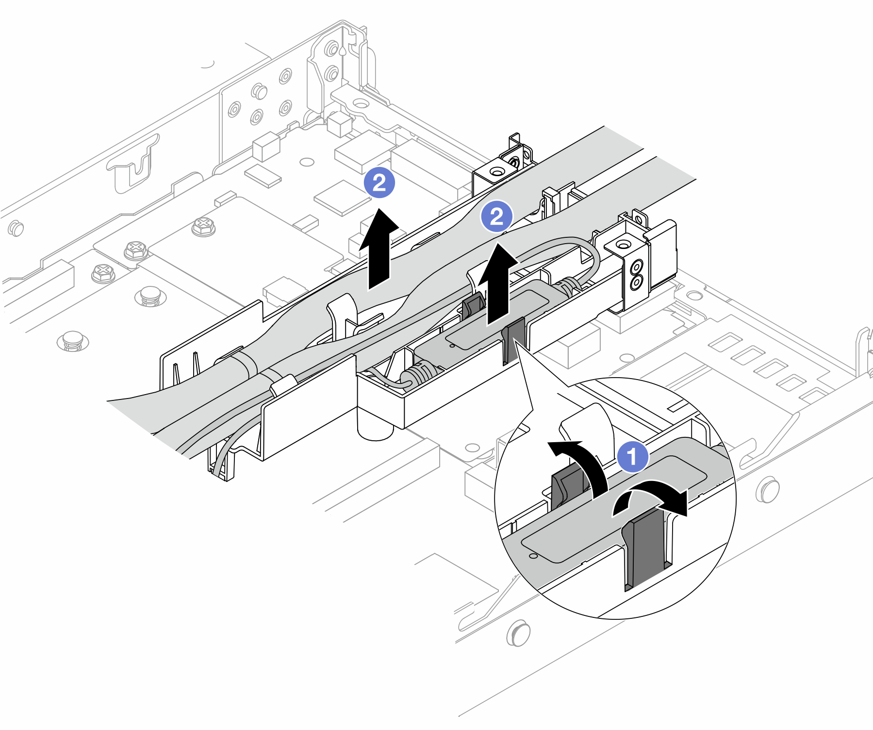
  6. Disengage the hoses and leakage detection sensor module.
    Figure 2. Disengaging the hoses and module

    1. Push the holder latches to both sides to unlock the module.
    2. Disengage the hoses and module from the hose holder.
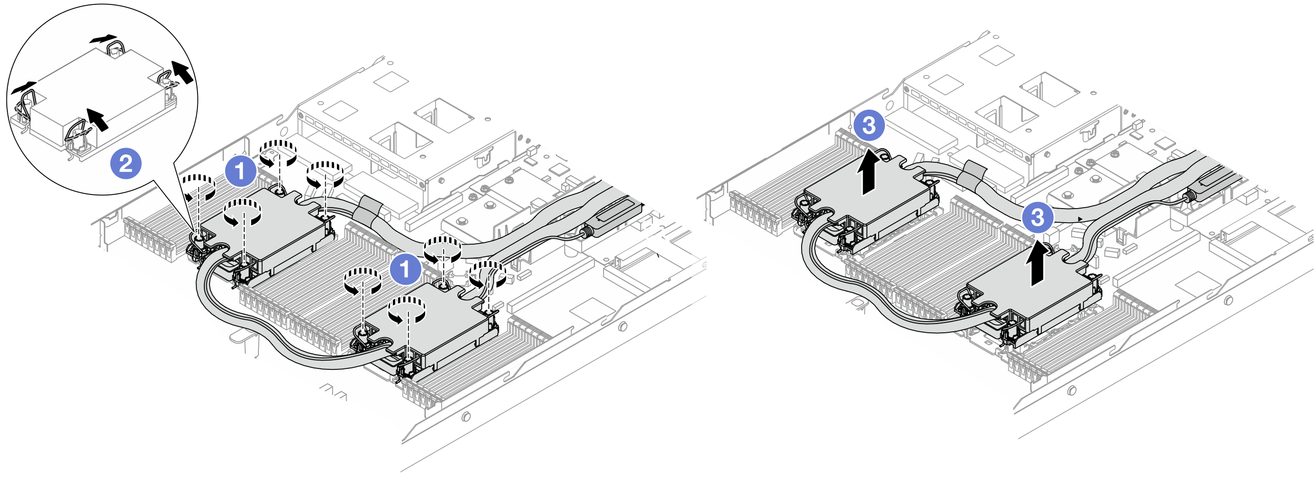
  7. Disengage the DWCM from the processor board.
    Figure 3. Removing the DWCM

    1. Fully loosen the Torx T30 nuts on the cold plate assembly.
    2. Rotate the anti-tilt wire bails inward.
    3. Carefully lift the DWCM from the processor sockets. If the DWCM cannot be fully lifted out of the socket, further loosen the Torx T30 nuts and try lifting the DWCM again.
  8. If there is any old thermal grease on the processors and the cold plates, gently clean the top of the processors and the cold plates with an alcohol cleaning pad.
  9. Separate the processor from the DWCM. Refer to Separate the processor from carrier and heat sink.
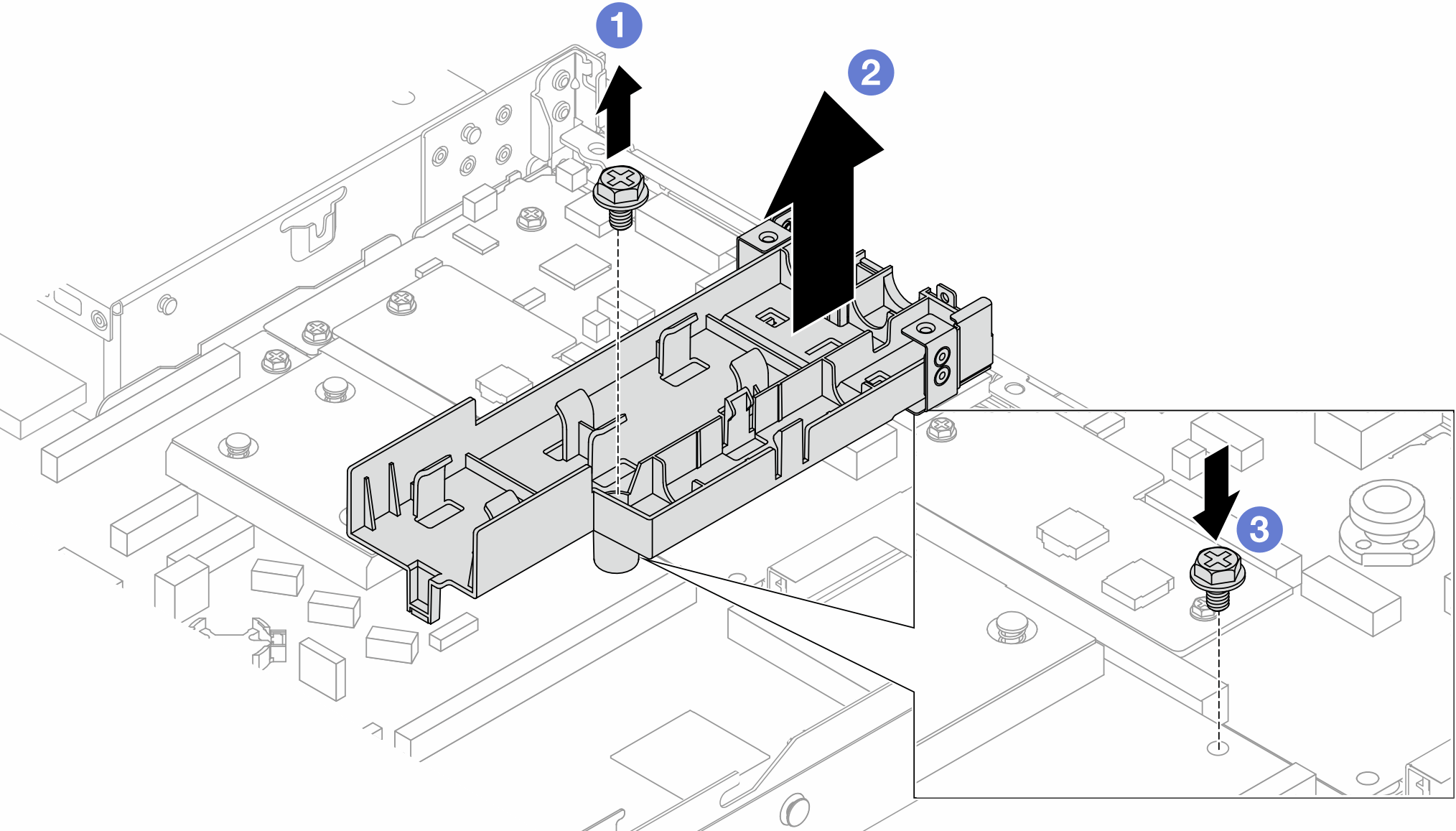
  10. Remove the hose holder.
    Figure 4. Removing the holder

    1. Loosen the screw that locks the holder to the processor board.
    2. Lift the holder out of the chassis.
    3. Re-install the screw back to the processor board.
After you finish

If you are instructed to return the component or optional device, follow all packaging instructions, and use any packaging materials for shipping that are supplied to you.

Demo video
Watch the procedure on YouTube