
Remove the front I/O assembly

Use this information to remove the front I/O assembly.

Before removing the front I/O assembly:
  1. Remove the top cover. See Remove the top cover.

  2. If the security bezel is installed, remove it. See Remove the security bezel.

  3. Disconnect cables of the front I/O assembly from the front I/O assembly.

    Attention
    Strictly observe the following instructions to avoid damaging cable sockets on the system board. Any damage to the cable sockets might require replacing the system board.
    • Connect cable connectors vertically or horizontally in alignment with the orientations of the corresponding cable sockets, avoiding any tilt.

    • To disconnect cables from the system board, do as follows:
      1. Press and hold all latches, release tabs, or locks on cable connectors to release the cable connectors.

      2. Remove the cable connectors vertically or horizontally in alignment with the orientations of the corresponding cable sockets, avoiding any tilt.
        Note
        The cable connectors might look different from those in the illustration, but the removal procedure is the same.


To remove the front I/O assembly, complete the following steps:

Table 1. Front I/O assembly removal
Figure 1. Server models with four 3.5-inch drive bays
Removal of the front I/O assembly for server models with four 3.5-inch drive bays

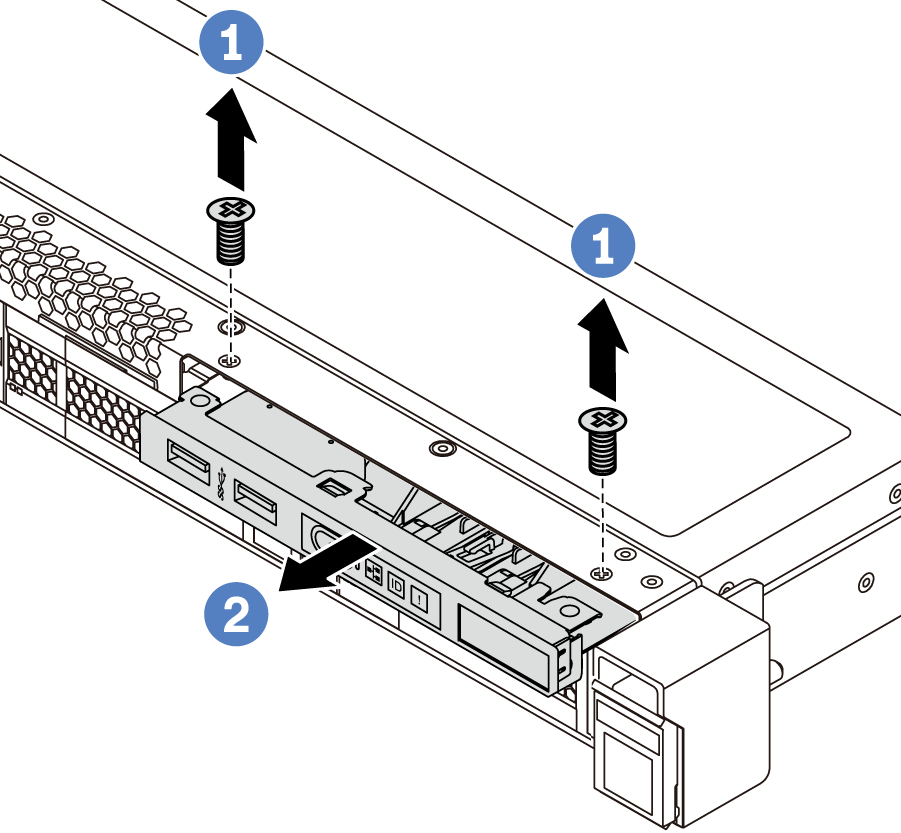
Figure 2. Server models with eight/ten 2.5-inch drive bays
Removal of the front I/O assembly for server models with ten 2.5-inch drive bays

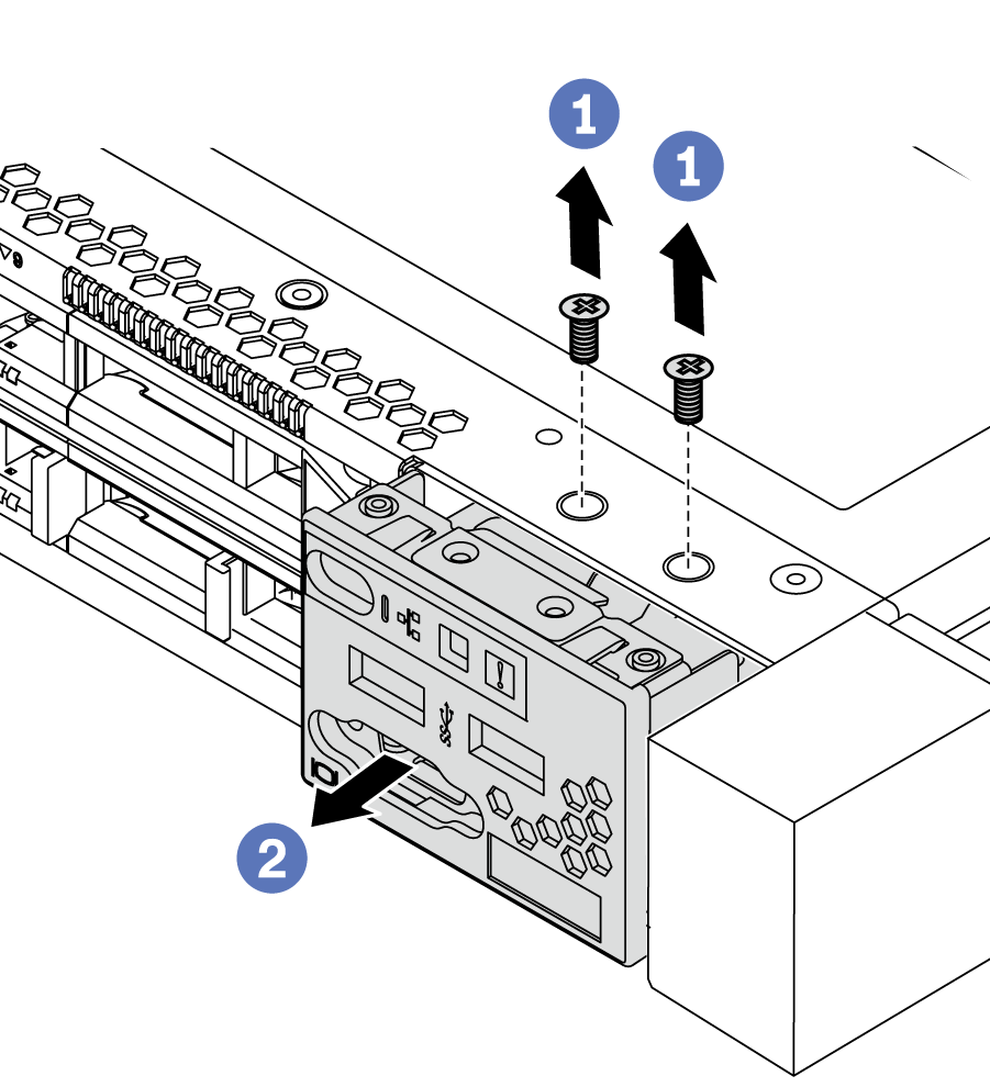
  1. Remove the screws that secure the front I/O assembly.
  2. Slide the front I/O assembly out of the assembly bay.
After you finish

If you are instructed to return the component or optional device, follow all packaging instructions, and use any packaging materials for shipping that are supplied to you.

Demo video

Watch the procedure on YouTube