10 x 2.5'' AnyBay backplane
Use this section to understand the AnyBay backplane cable routing for server model with ten 2.5'' front drives.
To connect power cables for a backplane for standard 2.5'' drives, refer to Backplane power cable routing.
To connect cables for M.2 drive backplane, refer to M.2 drive backplane.
To connect intrusion switch cable, refer to Intrusion switch.
To connect cables for RAID flash power modules, refer to RAID flash power modules
To connect signal cables for a backplane for standard 10 x 2.5'' front drives, refer to the following cable routing scenarios depending on your server configuration:
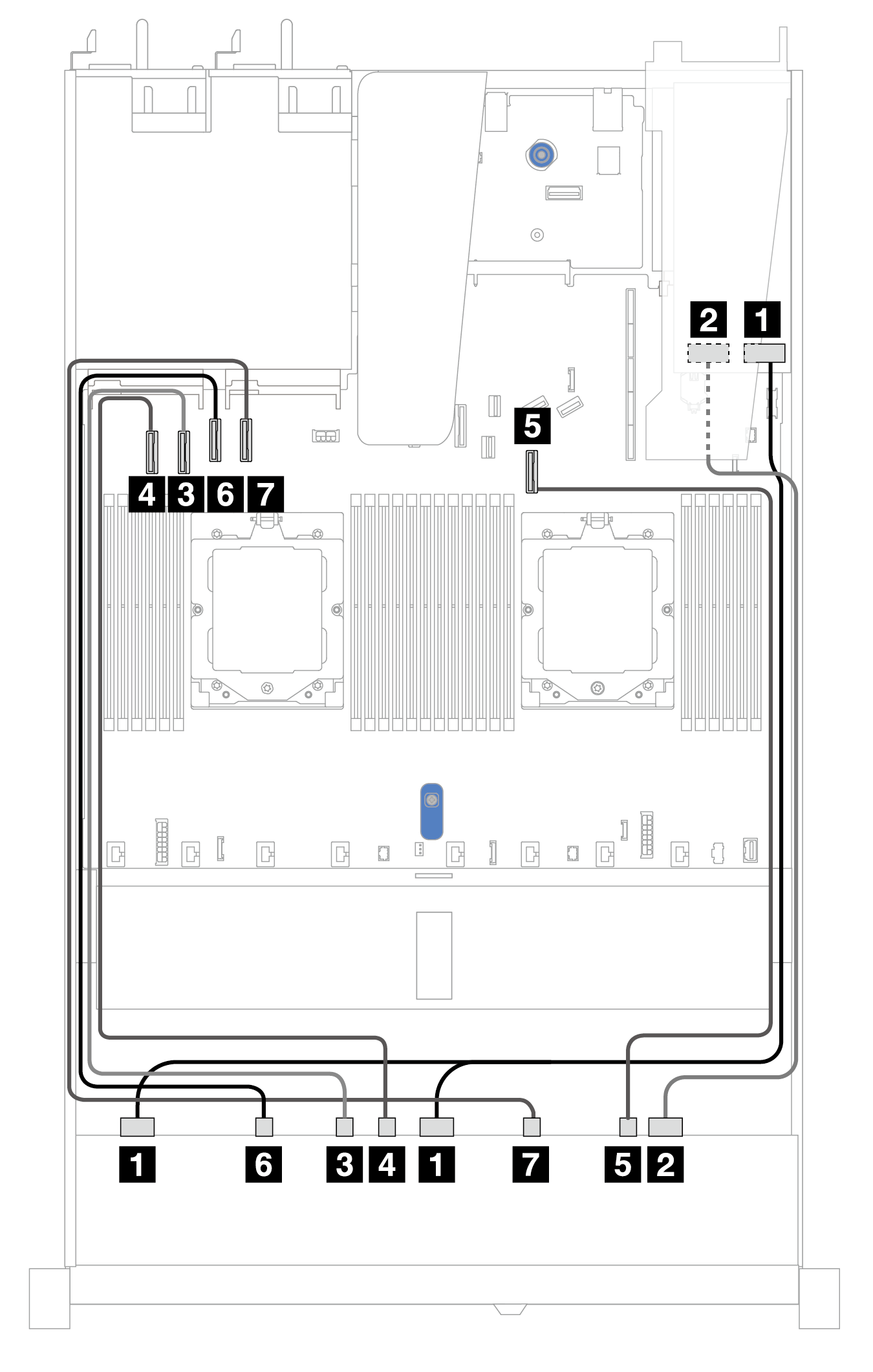
Cable routing with an SFF HBA/RAID adapter
The following tables show the mapping relationship between backplane connectors and an SFF HBA/RAID adapter (Gen 3 or Gen 4).
Figure 1. Cable routing for 10 AnyBay drives with a 16i SFF RAID adapter (Gen 3 or Gen 4)
| Backplane | From | To |
|---|---|---|
| Front BP (SAS) | 1 SAS 0, SAS 1 | 1
|
| 2 SAS 2 | 2
| |
| Front BP (NVMe) | 3 NVMe 2–3 | 3 PCIe 2 |
| 4 NVMe 4–5 | 4 PCIe 1 | |
| 5 NVMe 8–9 | 5 PCIe 7 | |
| 6 NVMe 0–1 | 6 PCIe 3 | |
| 7 NVMe 6–7 | 7 PCIe 4 |
Give documentation feedback