Gen4 riser card
Use the section to understand the cable routing for front riser assembly (Gen4).
For the locations of front PCIe adapter connector on the processor board, see System-board-assembly connectors for details.
The following illustrations and tables list the front PCIe adapters supported:
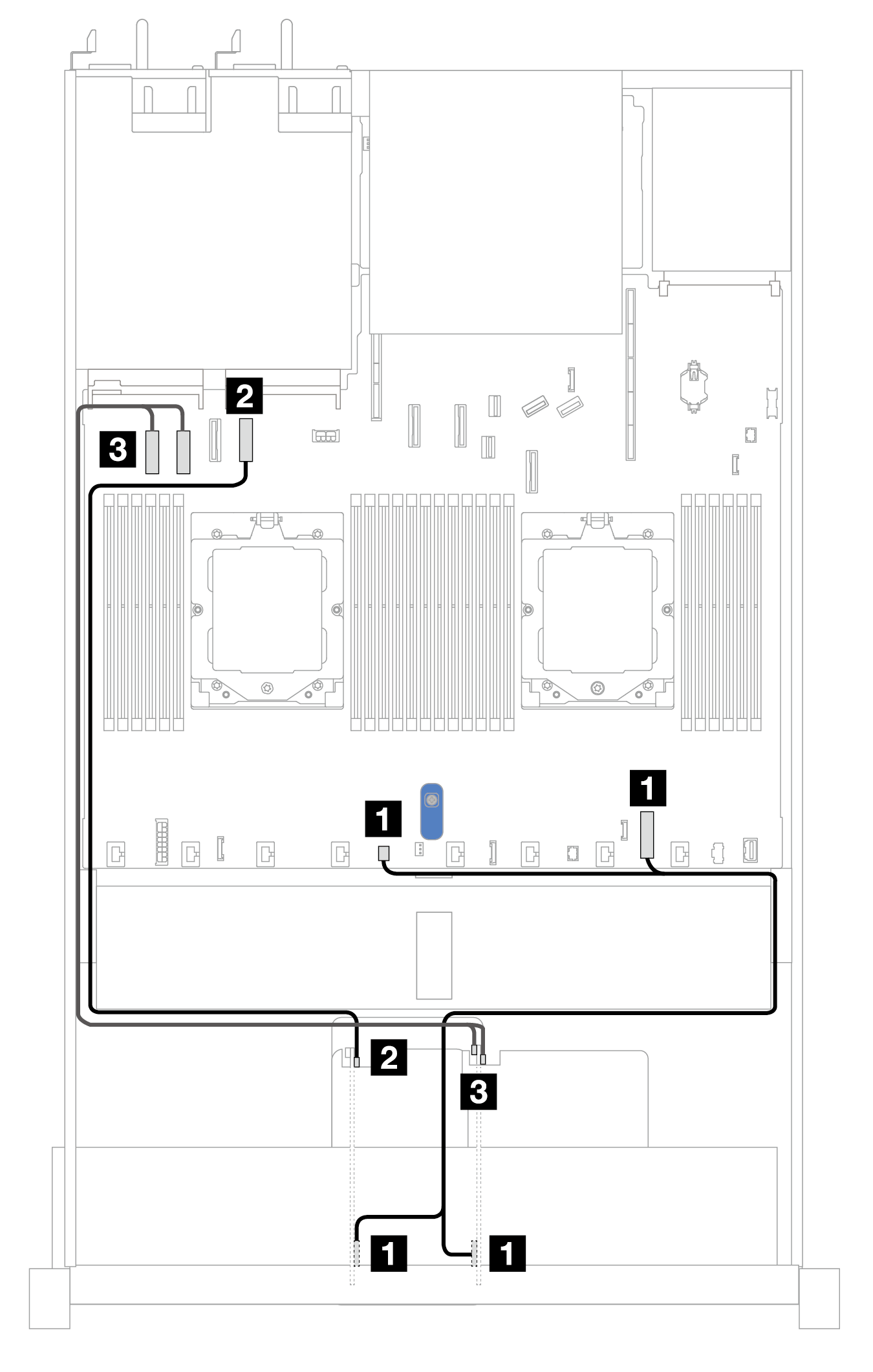
Cable routing with one x8 PCIe riser card and one x16 PCIe riser card
Figure 1. Cable routing with one x8 PCIe riser card and one x16 PCIe riser card
| From | To |
|---|---|
| 1 Power connectors on Risers 3 and 4 | 1 Internal RAID power connector and pump 2 connector on the processor board |
| 2 MCIO 1 connector on Riser 3 | 2 PCIe connector 4 on the processor board |
| 3 MCIO 1 and MCIO 2 connectors on Riser 4 | 3 PCIe connectors 1 and 2 on the processor board |
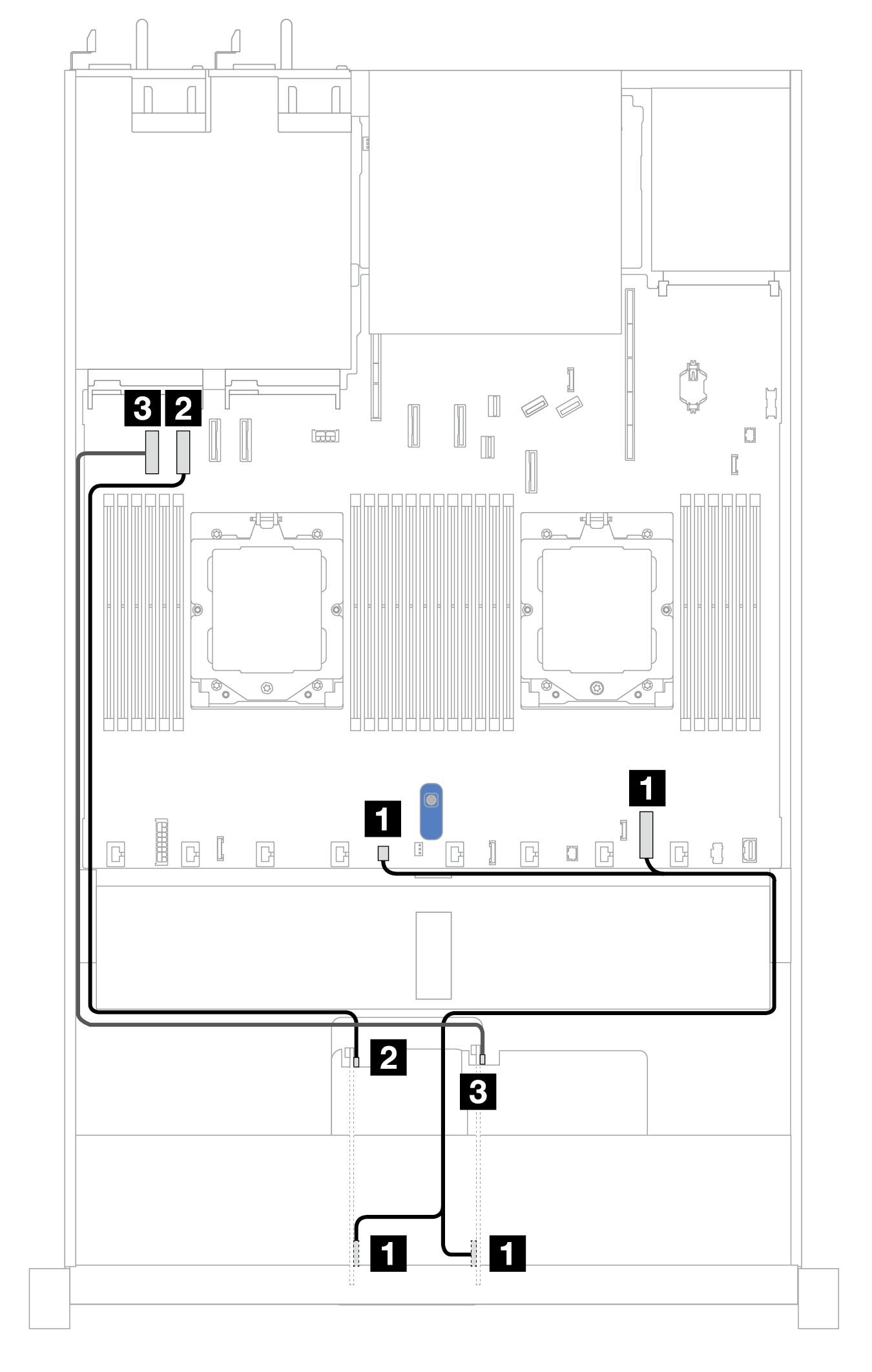
Cable routing with two x8 PCIe riser cards
Figure 2. Cable routing with two x8 PCIe riser cards
| From | To |
|---|---|
| 1 Power connectors on Risers 3 and 4 | 1 Internal RAID power connector and pump 2 connector on the processor board |
| 2 MCIO 1 connector on Riser 3 | 2 PCIe connector 2 on the processor board |
| 3 MCIO 1 connector on Riser 4 | 3 PCIe connector 1 on the processor board |
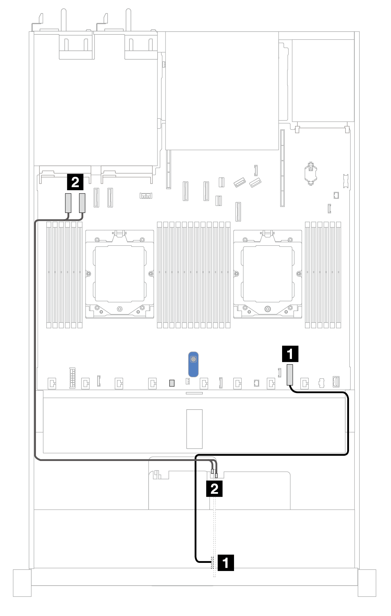
Cable routing with one x16 PCIe riser card
Figure 3. Cable routing with one x16 PCIe riser card
| From | To |
|---|---|
| 1 Power connector on Riser 4 | 1 Internal RAID power connector on the processor board |
| 2 MCIO 1 and MCIO 2 connectors on Riser 4 | 2 PCIe connectors 1 and 2 on the processor board |
Give documentation feedback