Install the front operator panel
Follow instructions in this section to install the front operator panel.
About this task
Attention
- Read Installation Guidelines and Safety inspection checklist to ensure that you work safely.
- Touch the static-protective package that contains the component to any unpainted metal surface on the server; then, remove it from the package and place it on a static-protective surface.
Procedure
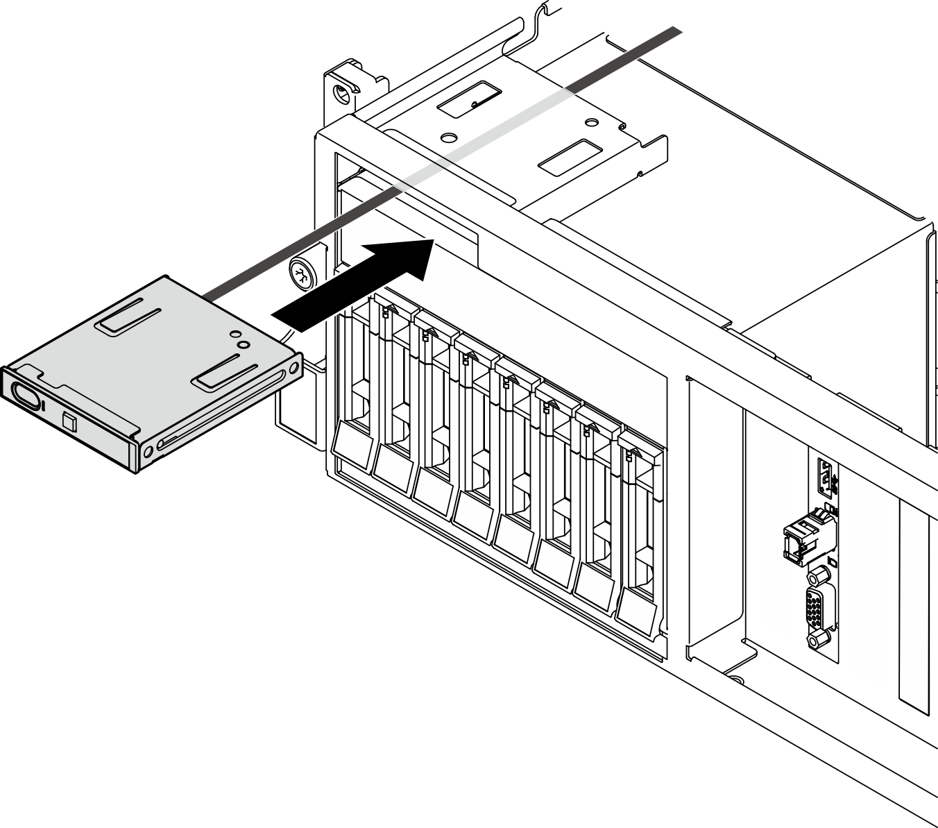
- Align the front operator panel with the slot on the top of the drive bays and slide it in.Figure 1. Front operator panel installation
- Connect the front operator panel cable to the system board assembly. Refer to the front operator panel cable routing guide for each server model below.Figure 2. Cable routing for the front operator panel — 4-DW GPU Model and 8-DW GPU ModelNoteThe
4-DW GPU Model is used as an example for illustration. The cable routing path is the same for the 8-DW GPU Model. 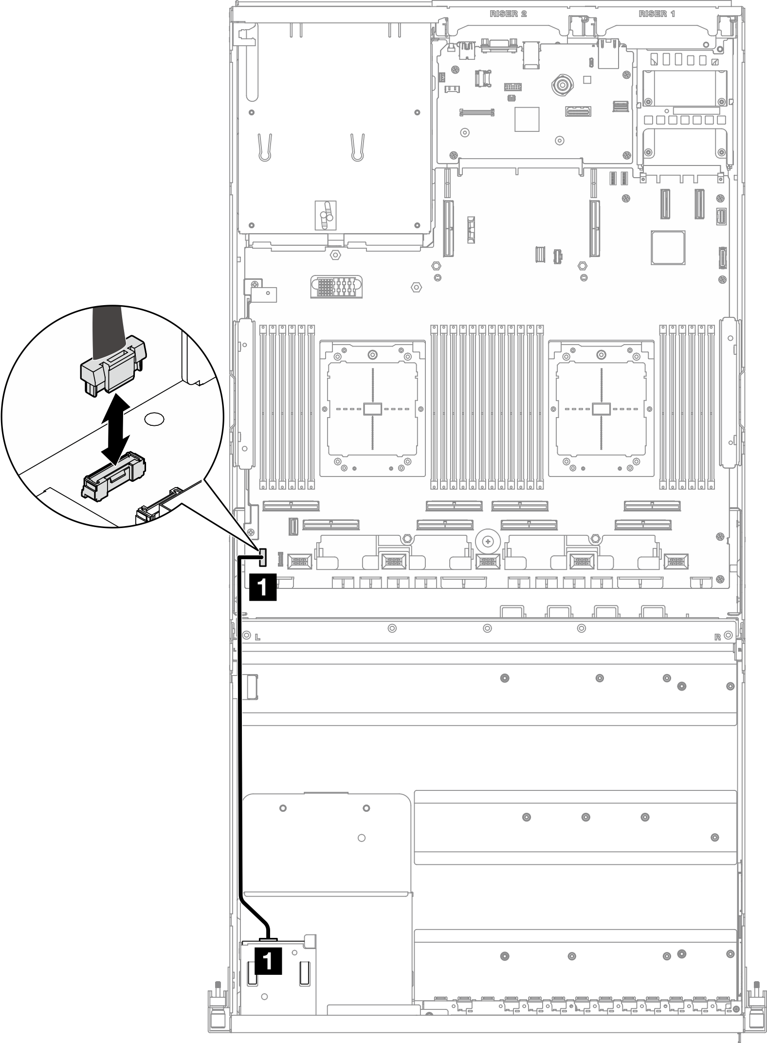 Figure 3. Cable routing for the front operator panel — SXM5 GPU Model
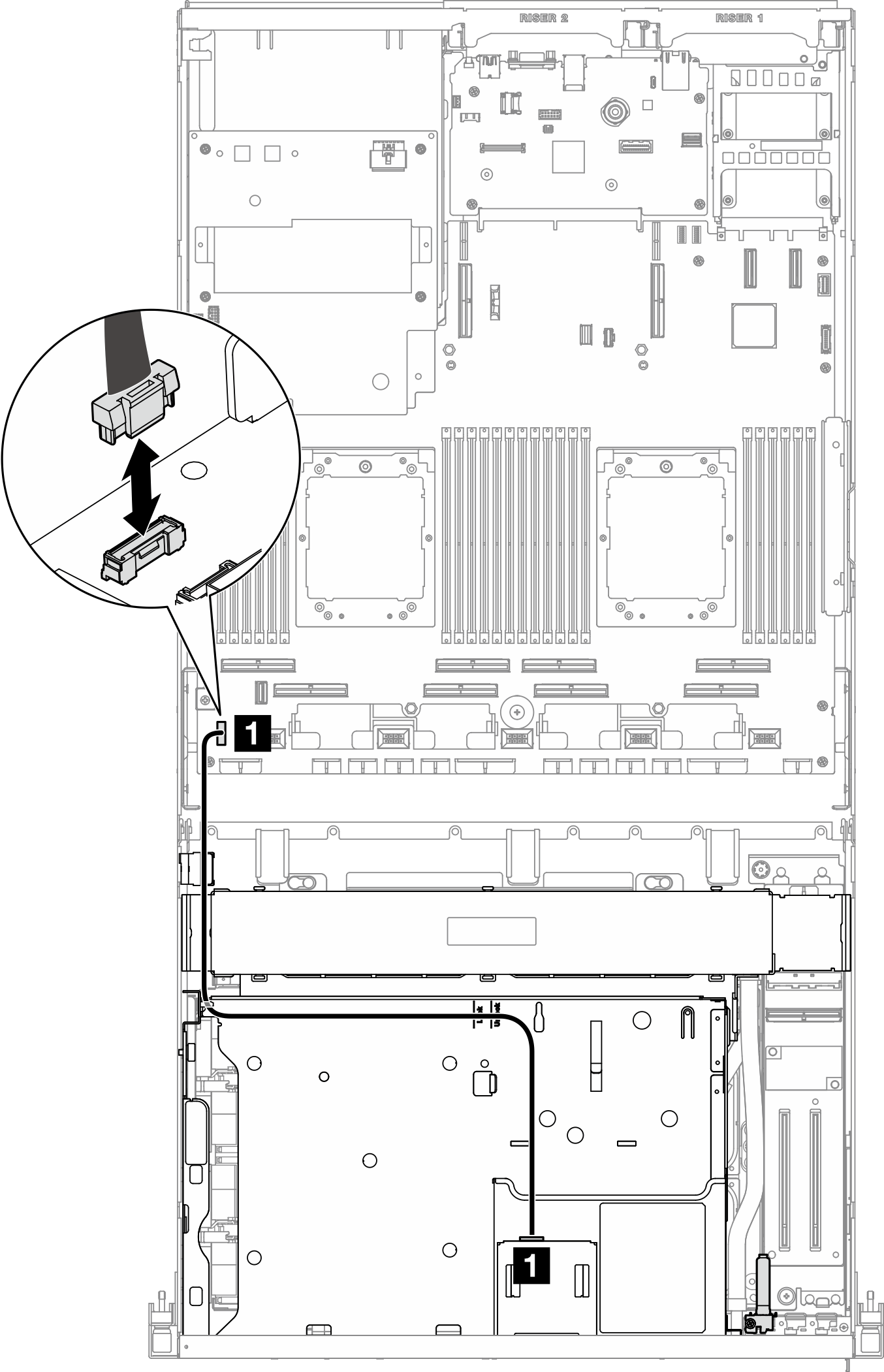
Cable From To 1 Front operator panel System board assembly: Front operator panel connector
After you finish
- (SXM5 GPU Model only) Depending on the configuration, reconnect the power cable to the CX-7 carrier board or the SXM5 PCIe switch board. See CX-7 carrier board cable routing or SXM5 PCIe switch board cable routing for more information. Then, press the power cable down to secure all the cables under the cable retaining guide on the front drive tray.
- Complete the parts replacement. See Complete the parts replacement.
Demo video
Give documentation feedback