Remove an MI300X GPU and heat sink module
Follow instructions in this section to remove an MI300X GPU and heat sink module. The procedure must be executed by a trained technician.
About this task
Attention
- Read Installation Guidelines and Safety inspection checklist to ensure that you work safely.
- Power off the server and peripheral devices and disconnect the power cords and all external cables. See Power off the server.
- Two people and one lifting device on site that can support up to 400 lb (181 kg) are required to perform this procedure. If you do not already have a lifting device available, Lenovo offers the Genie Lift GL-8 material lift that can be purchased at Data Center Solution Configurator. Make sure to include the Foot-release brake and the Load Platform when ordering the Genie Lift GL-8 material lift.
- Make sure to inspect the connectors and sockets on the GPU and the GPU baseboard. Do not use the GPU or the GPU baseboard if its connectors are damaged or missing, or if there are debris in the sockets. Replace the GPU or the GPU baseboard with a new one before continuing the installation procedure.
- GPU and heat sink is one part. Do not remove the heat sink from the GPU.
- The following table shows the mapping information about the physical GPU sockets and slot numbering in XCC.
Location of the GPU socket Physical GPU socket Slot numbering in XCC 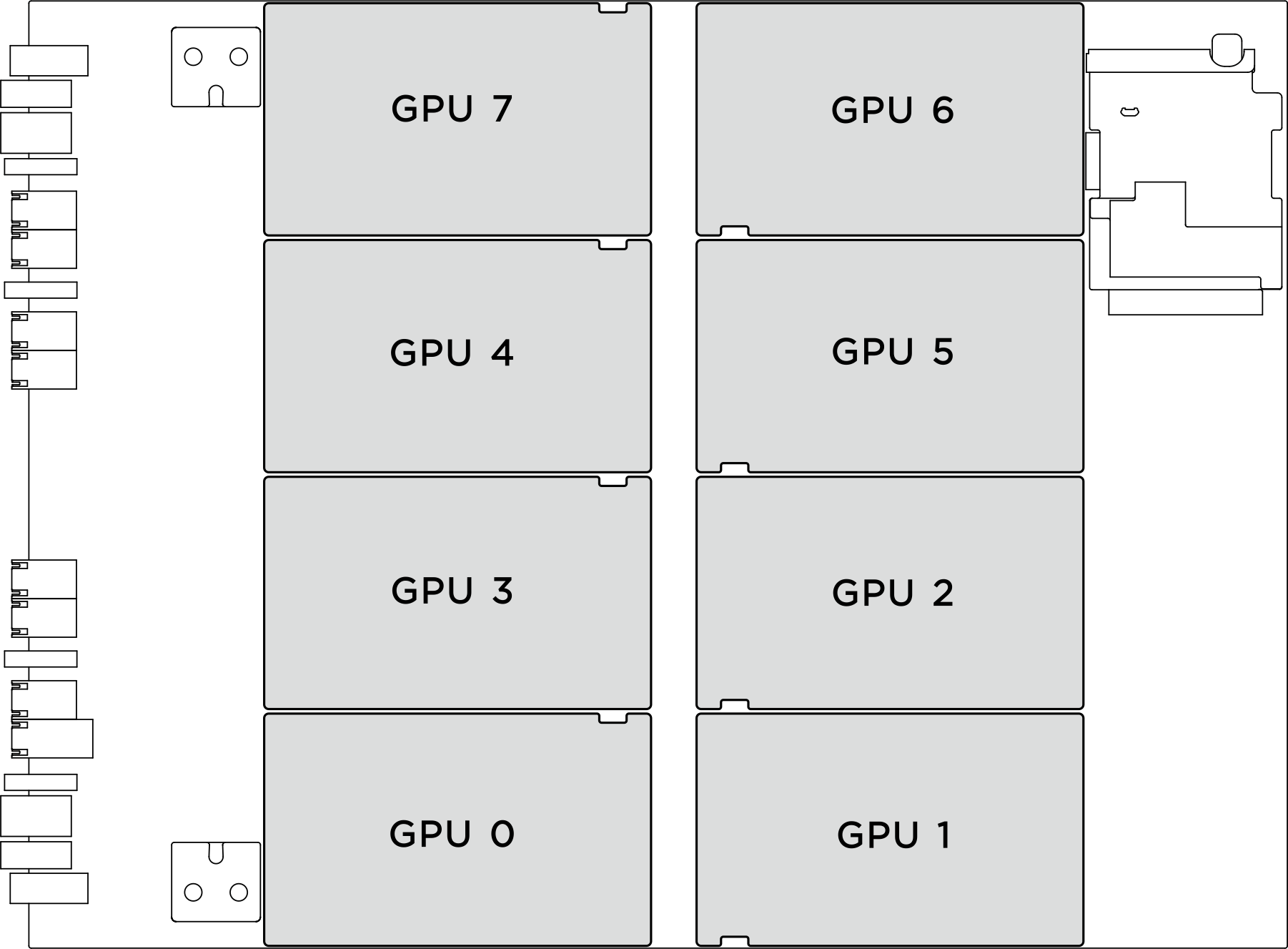
OAM 0 Slot 23 OAM 1 Slot 24 OAM 2 Slot 22 OAM 3 Slot 21 OAM 4 Slot 19 OAM 5 Slot 20 OAM 6 Slot 18 OAM 7 Slot 17
Note
Make sure you have the required tools listed below available to properly replace the component:
- Torque screwdriver which can be set to 1.53 newton-meters, 13.5 inch-pounds
- Torx T15 extended bit (200 mm long)
Procedure
- Make preparation for this task.
- Remove all the power supply units. See Remove a hot-swap power supply unit.
- Remove all the front fans. See Remove a hot-swap fan (front and rear).
- Remove all the 2.5-inch hot-swap drives and the drive bay fillers (if any) from the drive bays. See Remove a 2.5-inch hot-swap drive.
- Pull the 8U GPU shuttle out of the chassis, and place it onto the lift platform. See Remove the 8U GPU shuttle.
- Remove the power complex. See Remove the power complex.
- (GPU and heat sink module 0, 1, 6, and 7 only) Remove the GPU air duct. See Remove an MI300X GPU air duct.
- Remove the GPU and heat sink module.
 Unfasten the four screws in the removal sequence shown on the heat-sink label.NoteLoosen or tighten the screws with a torque screwdriver set to the proper torque. For reference, the torque required for the screws to be fully loosen or tighten is 1.53 newton-meters, 13.5 inch-pounds.
 Hold the handle (1) on the GPU and heat sink module; then, lift the GPU and heat sink module out of the GPU baseboard.Figure 1. GPU and heat sink module removal
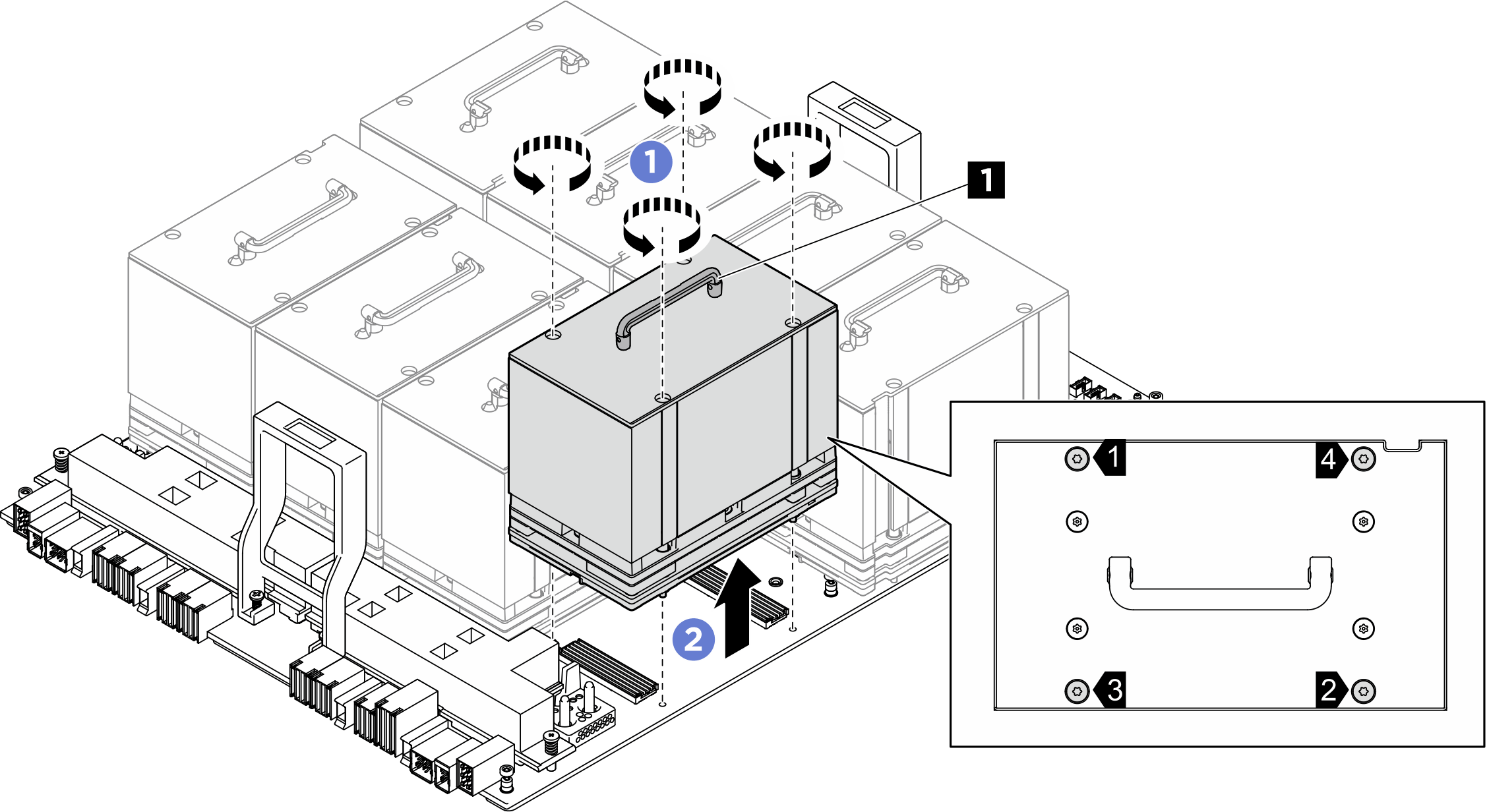
After you finish
If you are instructed to return the component or optional device, follow all packaging instructions, and use any packaging materials for shipping that are supplied to you.
Give documentation feedback