Install a memory module
Memory modules are in the system boards that are accessed from the front of the server.
See Memory module installation rules and order for detailed information about memory configuration and setup.
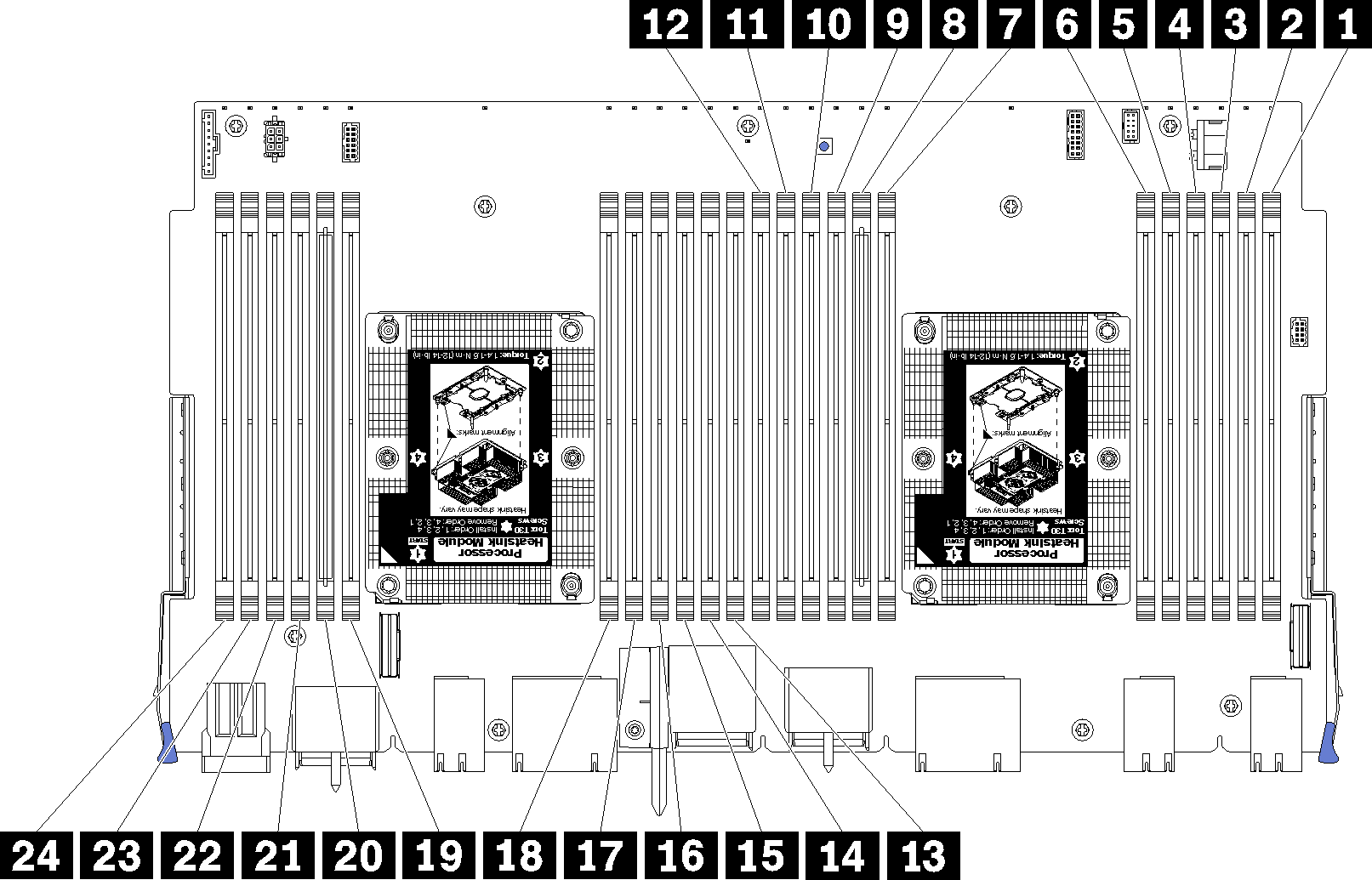
| DIMM number | System board 1 (lower board, lower tray) DIMM number | System board 2 (upper board, lower tray) DIMM number | System board 3 (lower board, upper tray) DIMM number | System board 4 (upper board, upper tray) DIMM number |
|---|---|---|---|---|
| 1 | 1 | 25 | 49 | 73 |
| 2 | 2 | 26 | 50 | 74 |
| 3 | 3 | 27 | 51 | 75 |
| 4 | 4 | 28 | 52 | 76 |
| 5 | 5 | 29 | 53 | 77 |
| 6 | 6 | 30 | 54 | 78 |
| 7 | 7 | 31 | 55 | 79 |
| 8 | 8 | 32 | 56 | 80 |
| 9 | 9 | 33 | 57 | 81 |
| 10 | 10 | 34 | 58 | 82 |
| 11 | 11 | 35 | 59 | 83 |
| 12 | 12 | 36 | 60 | 84 |
| 13 | 13 | 37 | 61 | 85 |
| 14 | 14 | 38 | 62 | 86 |
| 15 | 15 | 39 | 63 | 87 |
| 16 | 16 | 40 | 64 | 88 |
| 17 | 17 | 41 | 65 | 89 |
| 18 | 18 | 42 | 66 | 90 |
| 19 | 19 | 43 | 67 | 91 |
| 20 | 20 | 44 | 68 | 92 |
| 21 | 21 | 45 | 69 | 93 |
| 22 | 22 | 46 | 70 | 94 |
| 23 | 23 | 47 | 71 | 95 |
| 24 | 24 | 48 | 72 | 96 |
Complete the following steps to install a memory module:
Always wear an electrostatic-discharge strap when removing or installing memory modules. Electrostatic-discharge gloves can also be used.
Never hold two or more memory modules together so that they touch. Do not stack memory modules directly on top of each other during storage.
Never touch the gold memory module connector contacts or allow these contacts to touch the outside of the memory-module connector housing.
Handle memory modules with care: never bend, twist, or drop a memory module.
- Install the memory module.Figure 2. Memory module installation
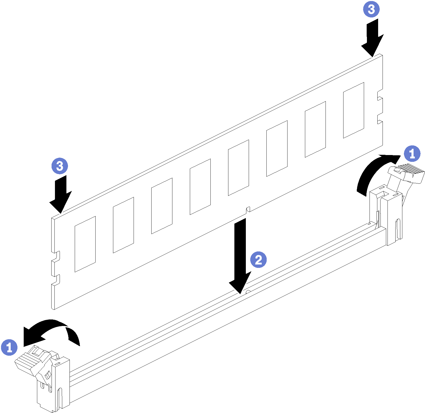
- Open the memory module connector retaining clips. If a memory module is already installed in the connector, remove it.
- Align the keys on the memory module that you are installing with the connector; then, insert the memory module.
- Firmly press both ends of the memory module straight down into the connector until the retaining clips snap into the locked position.
After you install a memory module:
Install the upper system board or system board filler, if it was removed. See Install a system board.
Install the compute tray where the system board is installed. See Install a compute tray.
Install the front cover. See Install the front cover
Power on the system.
If you have installed a DCPMM:
Update the system firmware to the latest version (see Update the firmware).
Make sure that the firmware on all of the DCPMM units is the latest version. If not, update it to the latest version (see Updating firmware on managed devices with LXCA).
Configure DCPMMs and DRAM DIMMs (see Configure DC Persistent Memory Module (DCPMM)).
Restore the data that have been backed up if necessary.
Demo video