Remove the riser for slot 10 to 15 (riser 2)
The riser for adapter slot 10 to 15 (riser 2) is in the I/O tray that is accessed from the rear of the server. After removing the I/O tray, loosen the two captive screws that secure the riser to the I/O tray; then, remove the riser from the I/O tray.
Before you remove the riser for slot 10 to 15, disconnect and label all cables connected to adapters in the I/O tray; then, remove the I/O tray. See Remove the I/O tray.
Complete the following steps to remove the riser for slot 10 to 15 (riser 2).
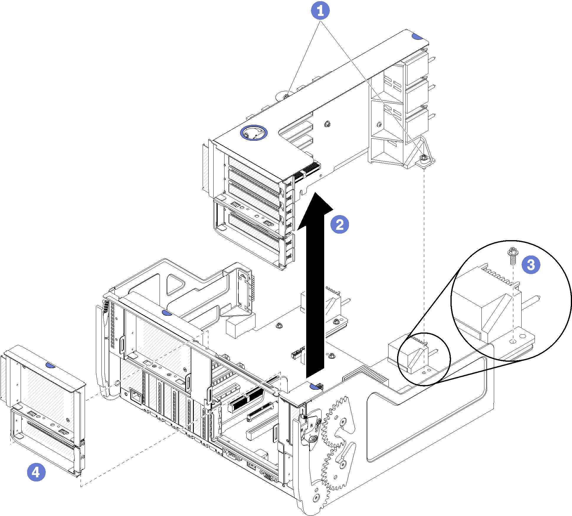
- Loosen the two captive screws (items 1 in preceding figure) that secure the riser to the I/O tray board.
- Lift the riser up and out of the I/O tray.
After you remove the riser:
If you are replacing the riser:
Remove any adapters installed in the riser. See Remove a PCIe adapter from slot 10 to 15.
If a slot 14 to 15 bracket is installed on the riser, remove it. See Remove the riser bracket for slot 14 to 15 (riser 2).
If you are removing the riser and are not installing a replacement:
Install the screw that secures the I/O tray board to the I/O tray (item 3 in the figure). This screw replaces the captive screw on the rear edge of the riser below the midplane connectors. Screw location is labelled
Remove screw before installing riser
on the I/O board.Install the I/O tray fillers in adapter slot 10 to 15 (item 4 in the figure).
Install the I/O tray and connect all cables. See Install the I/O tray.
If you are instructed to return the riser, follow all packaging instructions, and use any packaging materials for shipping that are supplied to you.
Demo video