Install a hot-swap power supply
Use this information to install a hot-swap power supply.


The standard shipping has only one power supply installed in the server. For redundancy and hot-swap support, you must install an additional hot-swap power supply. Certain customized models might be shipped with two power supplies installed.
Ensure that the devices that you are installing are supported. For a list of supported optional devices for the server, go to: Lenovo ServerProven website
NoteEnsure that the two power supplies installed on the server have the same wattage.
If you are replacing the existing power supply with a new power supply of different wattage, attach the power information label that comes with this option onto the existing label near the power supply.
Figure 1. Hot-swap power supply label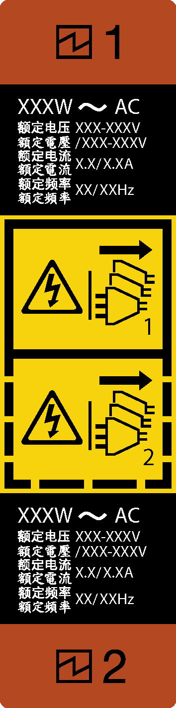
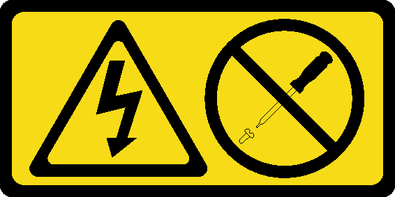
Never remove the cover on a power supply or any part that has this label attached. Hazardous voltage, current, and energy levels are present inside any component that has this label attached. There are no serviceable parts inside these components. If you suspect a problem with one of these parts, contact a service technician.

To avoid a shock hazard:
- Connect all power cords to a properly wired and grounded electrical outlet/source.
- Connect any equipment that will be attached to this product to properly wired outlets/sources.
- When possible, use one hand only to connect or disconnect signal cables.
- Never turn on any equipment when there is evidence of fire, water, or structural damage.
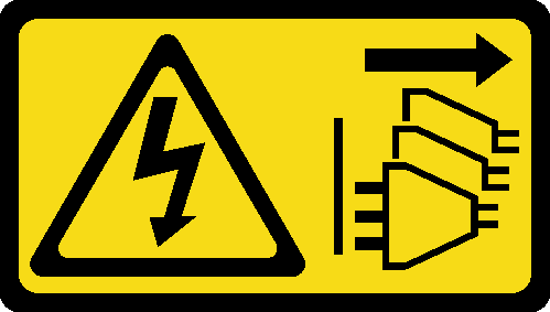
- The device might have more than one power cord, to remove all electrical current from the device, ensure that all power cords are disconnected from the power source.
The following tips describe the information that you must consider when you install a power supply with dc input.
NEVER CONNECT AND DISCONNECT THE POWER SUPPLY CABLE AND EQUIPMENT WHILE YOUR EQUIPMENT IS POWERED ON WITH DC SUPPLY (hot-plugging). Otherwise you may damage the equipment and result in data loss, the damages and losses result from incorrect operation of the equipment will not be covered by the manufacturers’ warranty.
Never remove the cover on a power supply or any part that has this label attached. Hazardous voltage, current, and energy levels are present inside any component that has this label attached. There are no serviceable parts inside these components. If you suspect a problem with one of these parts, contact a service technician.
To avoid a shock hazard:
- Do not connect or disconnect any cables or perform installation, maintenance, or reconfiguration of this product during an electrical storm.
- Connect all power cords to a properly wired and grounded power source.
- Connect to properly wired power sources any equipment that will be attached to this product.
- When possible, use one hand only to connect or disconnect signal cables.
- Never turn on any equipment when there is evidence of fire, water, or structural damage.
- Disconnect the attached ac power cords, dc power sources, network connections, telecommunications systems, and serial cables before you open the device covers, unless you are instructed otherwise in the installation and configuration procedures.
- Connect and disconnect cables as described in the following table when installing, moving, or opening covers on this product or attached devices.
| To Connect: | To Disconnect: |
|---|---|
|
|
Touch the static-protective package that contains the component to any unpainted metal surface on the server; then, remove it from the package and place it on a static-protective surface.
To install the hot-swap power supply, complete the following steps:
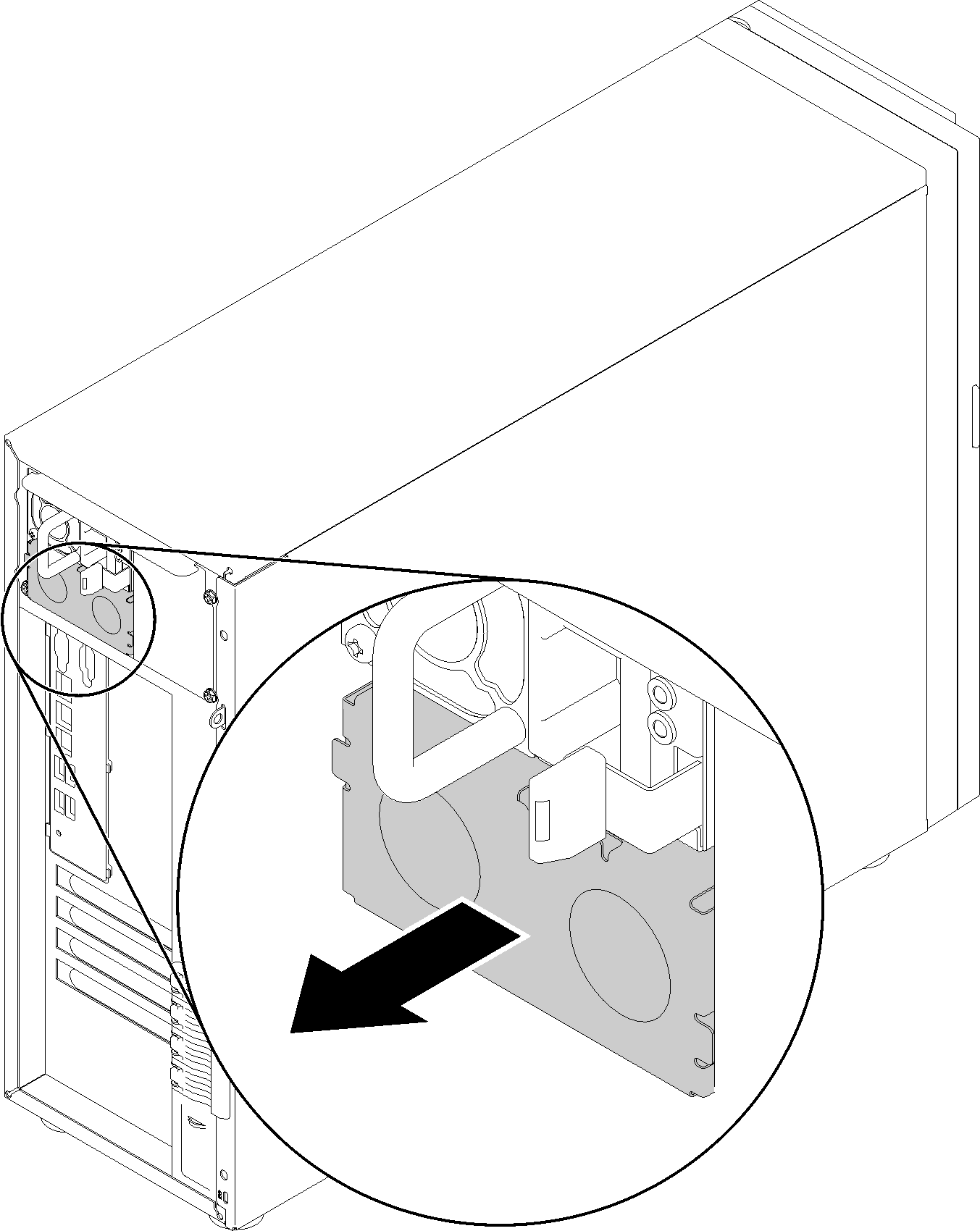
- If there is a power-supply-bay filler installed, remove it.ImportantTo ensure proper cooling during normal server operation, both of the power supply bays must be occupied. This means that each bay must have a power supply installed; or one has a power supply installed and the other has a power-supply filler installed.Figure 2. Hot-swap power supply filler removal
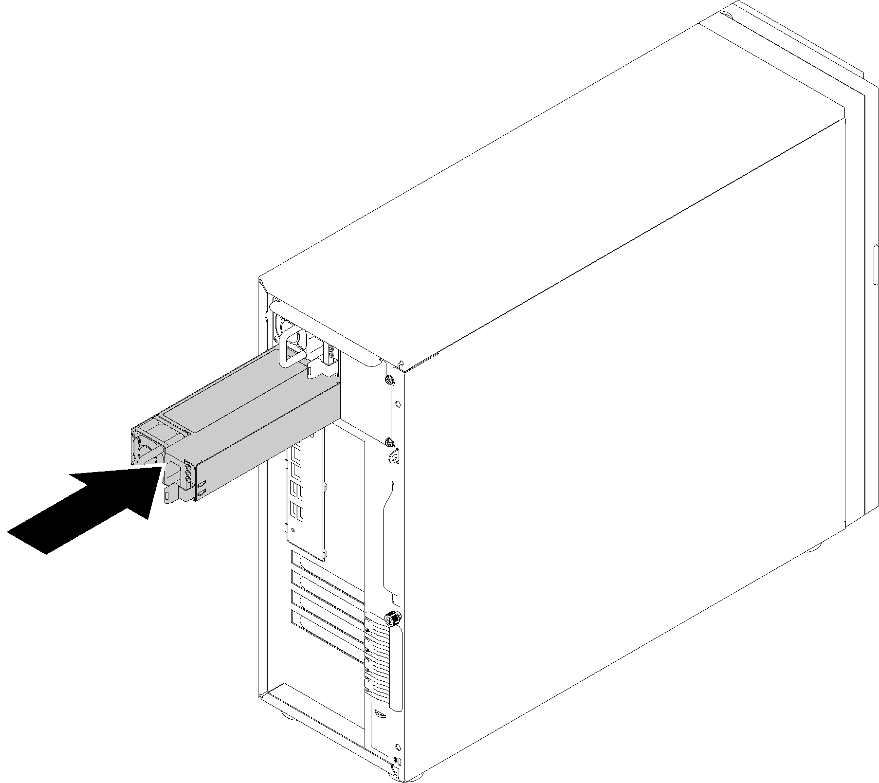
- Note the orientation of the hot-swap power supply, and then slide it into the chassis until it snaps into position.Figure 3. Hot-swap power supply installation
Demo video