Replacing the front USB connector assembly
Use this information to replace the front USB connector assembly
To install the front USB connector assembly on 4U server models with non-hot-swap power supplies, complete the following steps. For the 5U server model with hot-swap power supplies (Model name: 2582-F4x), please see the next sub-section.
- Read the safety information in Safety and Installation guidelines.
- Turn off the server and all attached devices; then, disconnect all power cords and external cables.
- Remove the bezel (see Removing the bezel).
- Carefully turn the server on its side so that it is lying flat, with the cover facing up.AttentionDo not allow the server to fall over.
- Remove the side cover (see Removing the side cover).
- Remove the air duct.
- Carefully insert the front USB cable through the opening in the front of the chassis.
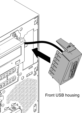
- Place the tab on the bottom edge of the USB housing into the bottom of the opening in the chassis.
- Tilt the top of the USB housing into position to the end.
- Secure the front USB housing with the screw.
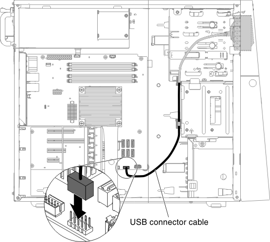
- Reroute and connect the front USB cable to the front USB connector on the system board (see System-board internal connectors for the location of the front USB connector).
- Install the air duct.
- Install the side cover (see Removing the side cover).
- Stand the server back up in its vertical position.
- Install bezel (see Replacing the bezel).
- Reconnect the external cables and power cords; then, turn on the attached devices and turn on the server.
To install the front-panel assembly on the 5U server model with hot-swap power supplies (Model name: 2582-F4x), complete the following steps. For 4U server models with non-hot-swap power supplies, please see the above sub-section.
- Read the safety information in Safety and Installation guidelines.
- Turn off the server and all attached devices; then, disconnect all power cords and external cables.
- Unlock and remove the side cover (see Removing the side cover).
- Remove the lower bezel (see Removing the lower bezel).
- Remove the upper bezel (see Removing the upper bezel).
- Carefully insert the front USB cable through the opening in the front of the chassis.
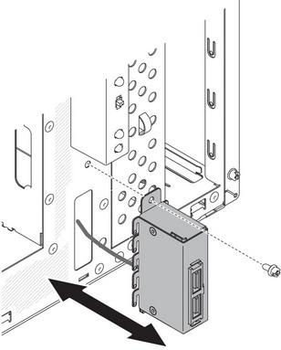
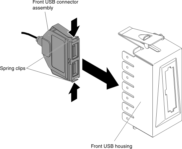
- Squeeze the spring clips on the sides of the front USB connector assembly and insert the assembly into the housing through the back of the housing.
- Place the bottom edge of the housing into the bottom of the opening in the chassis; then, tilt the top of the housing into position until it clicks into place.
- Carefully turn the server on its side so that it is lying flat, with the cover facing up.AttentionDo not allow the server to fall over.
- Reroute and connect the front USB cable to the front USB connector on the system board (see System-board internal connectors for the location of the front USB connector).
- Stand the server back up in its vertical position.
- Install the upper bezel (see Replacing the upper bezel).
- Install the lower bezel (see Replacing the lower bezel).
- Install and lock the side cover (see Replacing the side cover).
- Reconnect the external cables and power cords; then, turn on the attached devices and turn on the server.
Give documentation feedback