DIMM installation sequence
When you install additional DIMMs, install them in the order shown in the following table to optimize system performance.
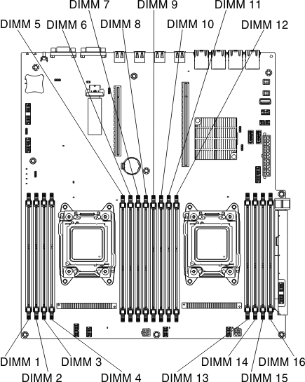
Figure 1. System board DIMM connectors
| Number of installed microprocessors | DIMM connector population sequence |
|---|---|
| 1 | 8, 6, 1, 3, 7, 5, 2, 4 |
| 2 | 8, 16, 6, 14, 1, 9, 3, 11, 7, 15, 5, 13, 2, 10, 4, 12 |
The following tables lists the DIMM connectors on each memory channel.
| Number of installed microprocessors | Memory channel | DIMM connectors |
|---|---|---|
| Microprocessor 1 | Channel 1 | 7, 8 |
| Channel 2 | 5, 6 | |
| Channel 3 | 1, 2 | |
| Channel 4 | 3, 4 |
The following table lists the DIMM connectors on each memory channel.
| Number of installed microprocessors | Memory channel | DIMM connectors |
|---|---|---|
| Microprocessor 2 | Channel 1 | 15, 16 |
| Channel 2 | 13, 14 | |
| Channel 3 | 9, 10 | |
| Channel 4 | 11, 12 |
Give documentation feedback