Replacing an adapter
Use this information to replace an adapter.
The following notes describe the types of adapters that the server supports and other information that you must consider when you install an adapter:
- Locate the documentation that comes with the adapter and follow those instructions in addition to the instructions in this section.
- The server provides one internal SAS/SATA RAID connector and two PCI slots on the system board. See System-board optional-device connectors for the location of the internal SAS/SATA RAID connector and riser-card slots. You can replace the ServeRAID SAS/SATA adapter with an optional ServeRAID SAS/SATA adapter in the slot. For configuration information, see the ServeRAID documentation at the Lenovo Support Portal.
- Do not set the maximum digital video adapter resolution above 1600 x 1200 at 75 Hz for an LCD monitor. This is the highest resolution that is supported for any add-on video adapter that you install in the server.
- Read the following table before installing memory modules when any NVIDIA Quadro adapters is installed.
Table 1. NVIDIA Quadro video adapter configurations Description Supported maximum total memory size Quadro 600 adapter 128 GB Quadro 2000 adapter 512 GB Quadro 4000 adapter 512 GB Quadro 6000 adapter 512 GB - Any high-definition video-out connector or stereo connector on any add-on video adapter is not supported
- The server does not support legacy 5V PCI adapters.
- When you install any PCI adapter, the power cords must be disconnected from the power source before you remove the PCI Express riser-card assembly and the PCI-X riser-card assembly. Otherwise, the active power management event signal will be disabled by the system-board logic, and the Wake on LAN feature might not work. However, after the server is powered-on locally, the active power manager active power management event signal will be enabled by the system-board logic.
- The server provides two PCI riser-card slots on the system board. If you want to install a PCI Express or PCI-X adapter, you must order the PCI riser-card option.
- If you are installing a ServeRAID-M5110, ServeRAID-M5120, or an LLM-SM dual port 10GbE SFP+ adapter, it can only be installed in PCI slot 1, 2, 4, or 5.
- Before you install an additional adapter, go to Table 2 for detailed power supply configurations.
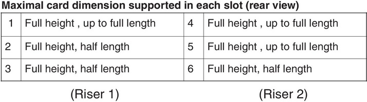
The following illustration shows the locations of the adapter expansion slots from the rear of the server.
To install an adapter, complete the following steps:
Note
If your adapter was previously configured, backup or record its configuration information, if possible, before replacing the adapter. See the documentation for your adapter for information and instructions.
If you are replacing a ServeRAID adapter, import your RAID configuration to the replacement adapter as a foreign configuration after you finish the replacement. See the ServeRAID-M Software User Guide for instructions.
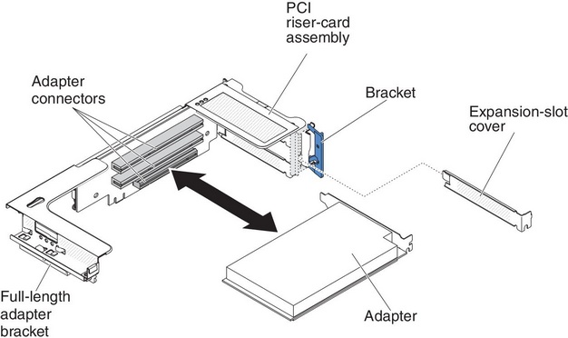
Figure 1. Adapter installation
- Install the adapter in the expansion slot.
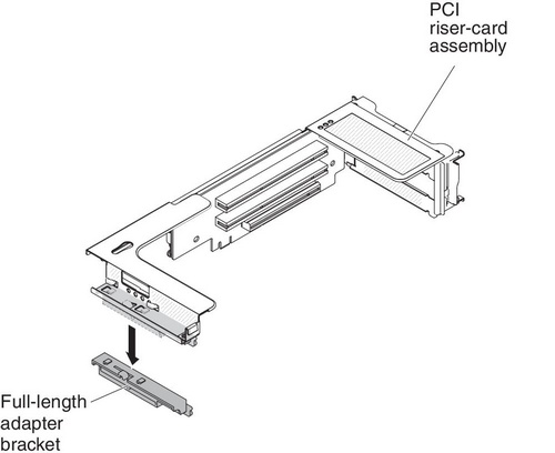
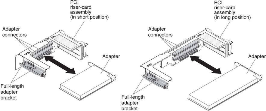
- For riser 1: if the adapter is a full-length adapter for the upper expansion slot in the riser card, remove the full-length-adapter bracket from underneath the top of the riser-card assembly and insert it in the end of the upper expansion slot of the riser-card assembly. See Stretching a PCI riser-card assembly for instructions.
- For riser 2: if the adapter is a full-length adapter for the upper expansion slot in the riser card, the bracket is on the cage by default. Insert it in the end of the upper expansion slot of the riser-card assembly. See Stretching a PCI riser-card assembly for instructions.
- Align the adapter with the PCI connector on the riser card and the guide on the external end of the riser-card assembly.
- Press the adapter firmly into the PCI connector on the riser card.
Give documentation feedback