Install the foolproof module
Use this information to install the foolproof module.
About this task
Attention
Read Installation Guidelines and Safety inspection checklist to ensure that you work safely.
Watch the procedure
- A video of this procedure is available at YouTube.
Procedure
- Install the foolproof module to the tray.
 Install the foolproof module to the tray.
 From outside of the tray, install two screws to secure the foolproof module to the tray.Figure 1. Installing the foolproof module
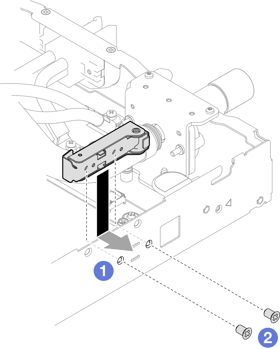
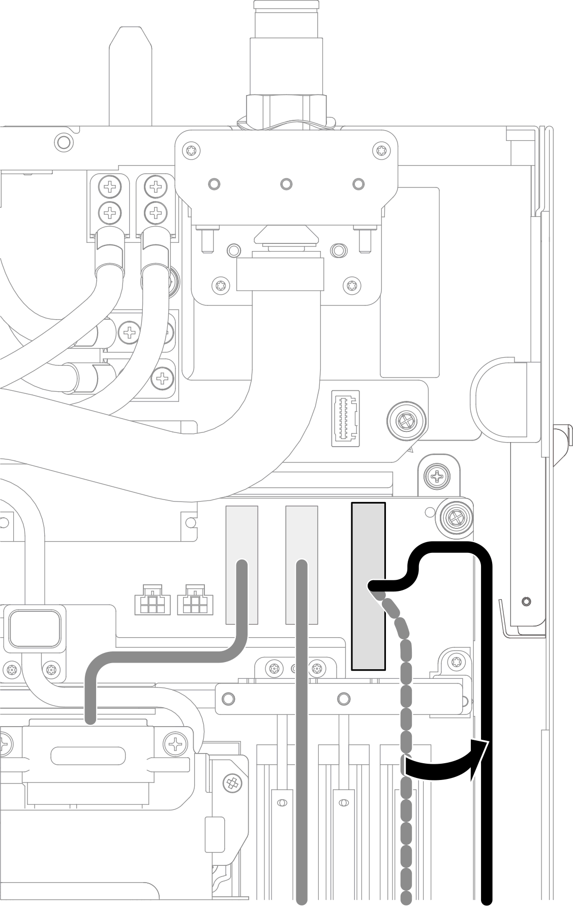
- Place the front drive cable beside the water loop.Figure 2. Placing the front drive cable beside the water loop
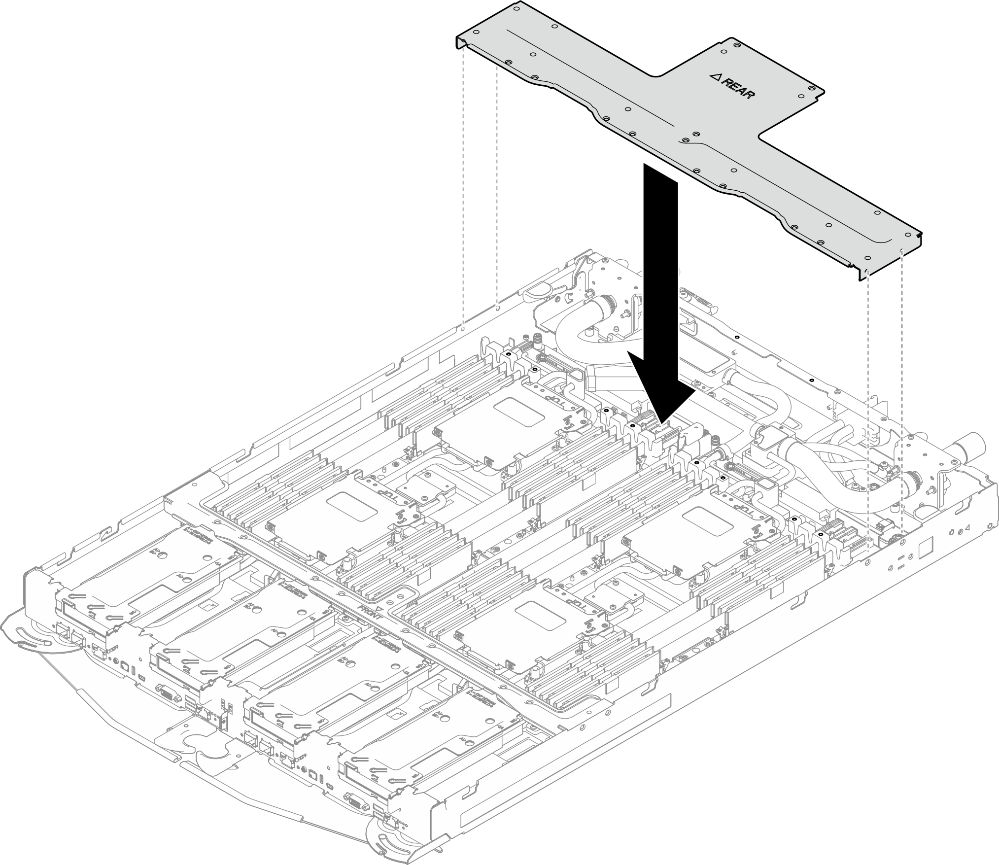
- Place the rear cross brace on the tray.Figure 3. Placing rear cross brace on the tray
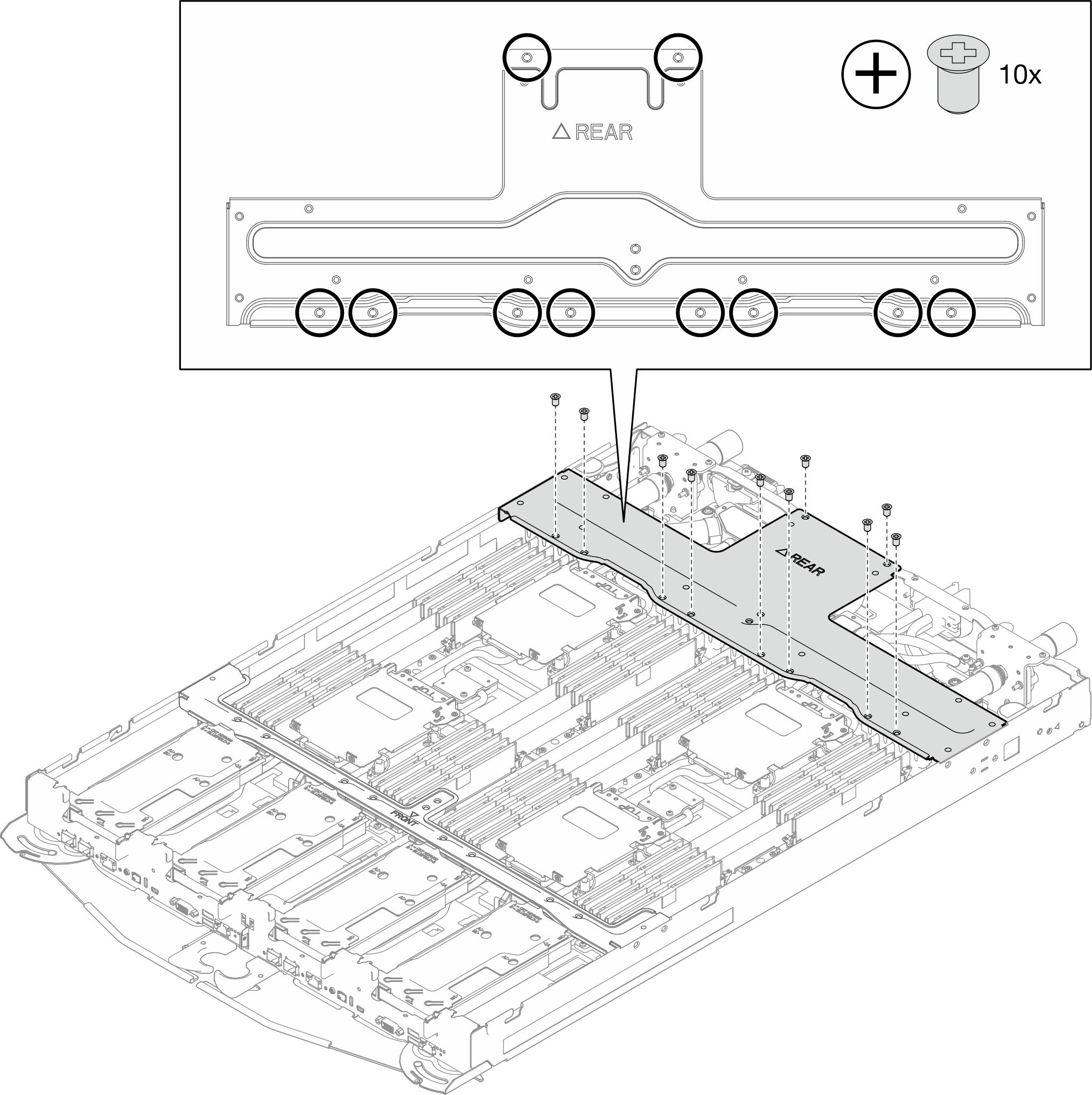
- Install the rear cross braces to the tray.
- Install ten (10x) PH1 screws to secure the rear cross brace.Figure 4. Installing screws to the rear cross brace (10x)
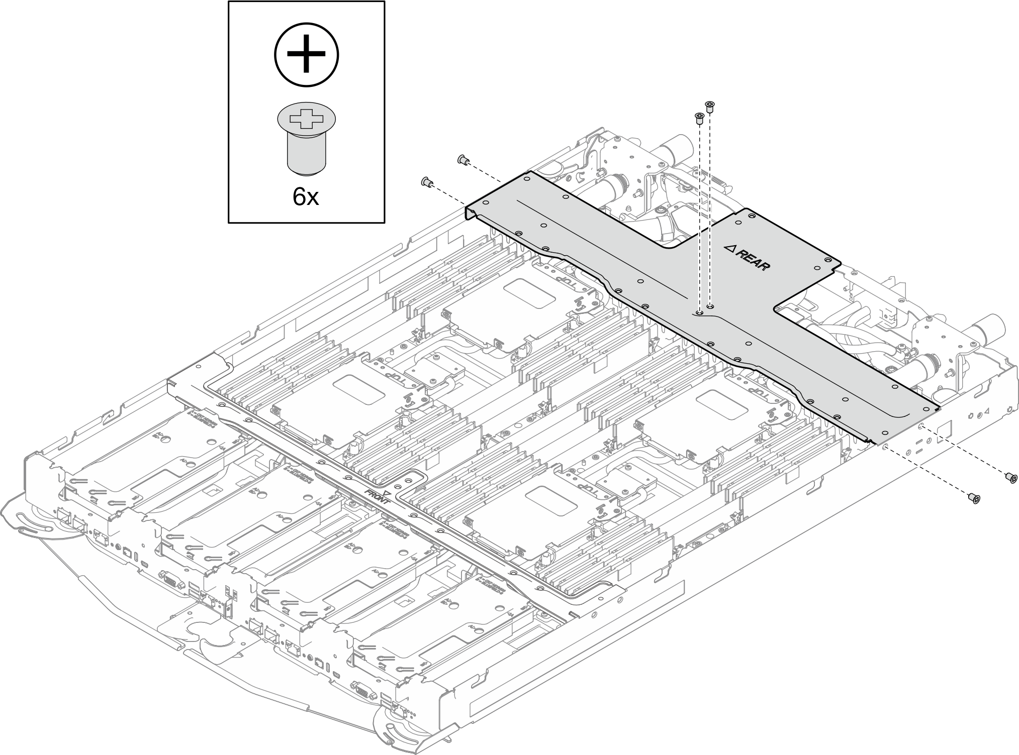
- Fasten six (6x) PH1 screws to install the cross braces.Figure 5. Installing screws to the rear cross brace (6x)
- Install ten (10x) PH1 screws to secure the rear cross brace.
After you finish
Install the tray cover. See Install the tray cover.
Install the tray into the enclosure. See Install a tray in the enclosure.
- Connect all required external cables to the solution.NoteUse extra force to connect QSFP cables to the solution.
- Check the power LED on each node to make sure it changes from fast blink to slow blink to indicate all nodes are ready to be powered on.Note
Shared I/O configuration requires specific nodes power-on sequence. When powering on the system, power on Node B first; then, power on Node A. For more information, see PCIe adapter cable routing.
Give documentation feedback