Remove a memory module (single-side cooling)
Use this information to remove a memory module that requires single-side cooling.
32GB, 64GB, and 96GB RDIMM require single-side cooling. (128GB RDIMM, 32GB MRDIMM, 64GB MRDIMM require dual-side cooling, refer to Memory module (dual-side cooling) replacement.)
About this task
Read Installation Guidelines and Safety inspection checklist to ensure that you work safely.
Turn off the corresponding DWC tray that you are going to perform the task on.
Disconnect the power cords and all external cables from the enclosure.
Disconnect the power cords from the enclosure.
Make sure to remove or install memory module 20 seconds after disconnecting power cords from the system. It allows the system to be completely discharged of electricity and safe for handling memory module.
Use extra force to disconnect QSFP cables if they are connected to the solution.
Memory modules are sensitive to static discharge and require special handling. In addition to the standard guidelines for Handling static-sensitive devices:
Always wear an electrostatic-discharge strap when removing or installing memory modules. Electrostatic-discharge gloves can also be used.
Never hold two or more memory modules together so that they touch. Do not stack memory modules directly on top of each other during storage.
Never touch the gold memory module connector contacts or allow these contacts to touch the outside of the memory-module connector housing.
Handle memory modules with care: never bend, twist, or drop a memory module.
The following illustration might differ slightly from your hardware, but the installation method is the same.
- A video of this procedure is available at YouTube.
Procedure
Make sure to remove or install memory module 20 seconds after disconnecting power cords from the system. It allows the system to be completely discharged of electricity and safe for handling memory module.
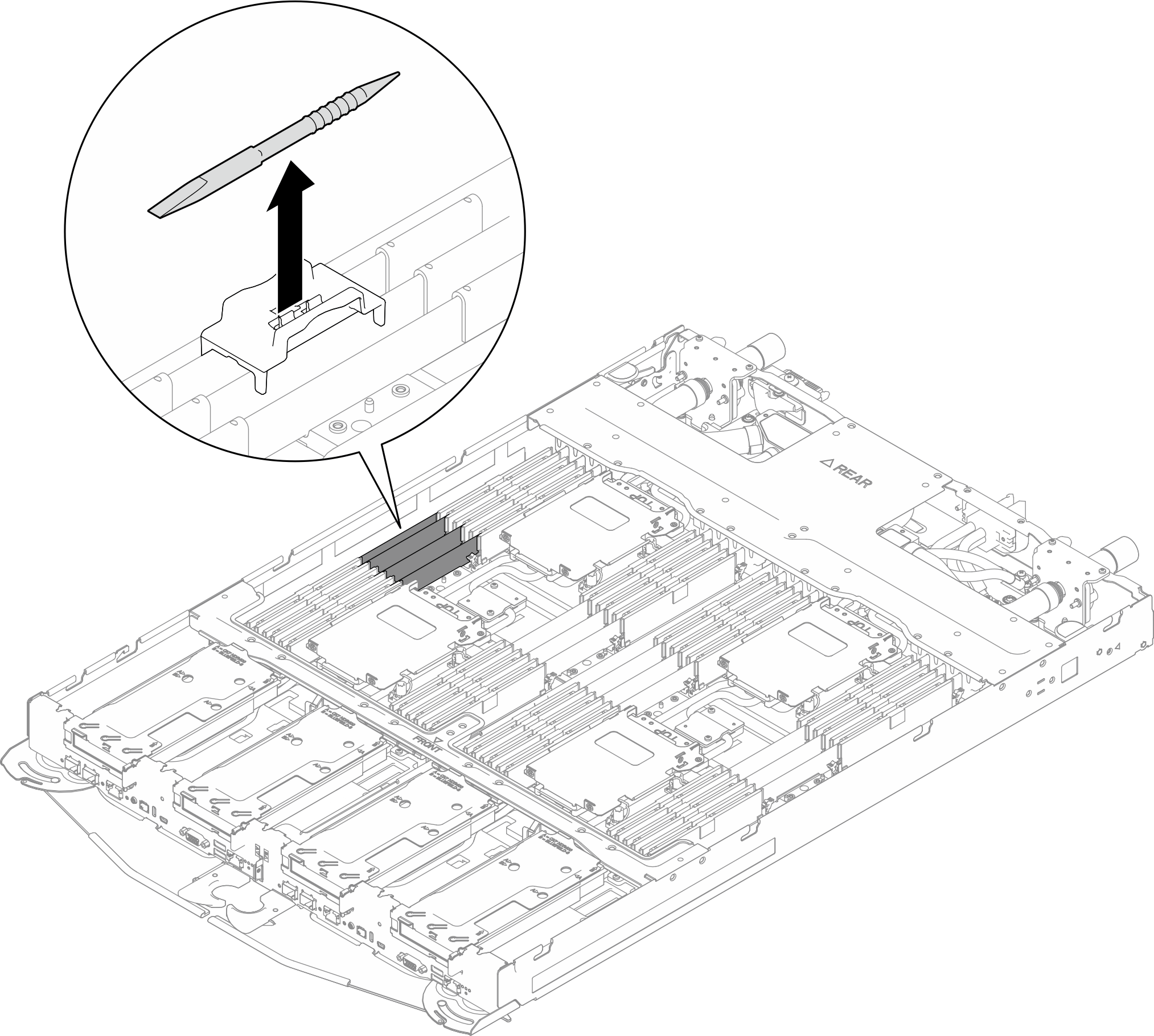
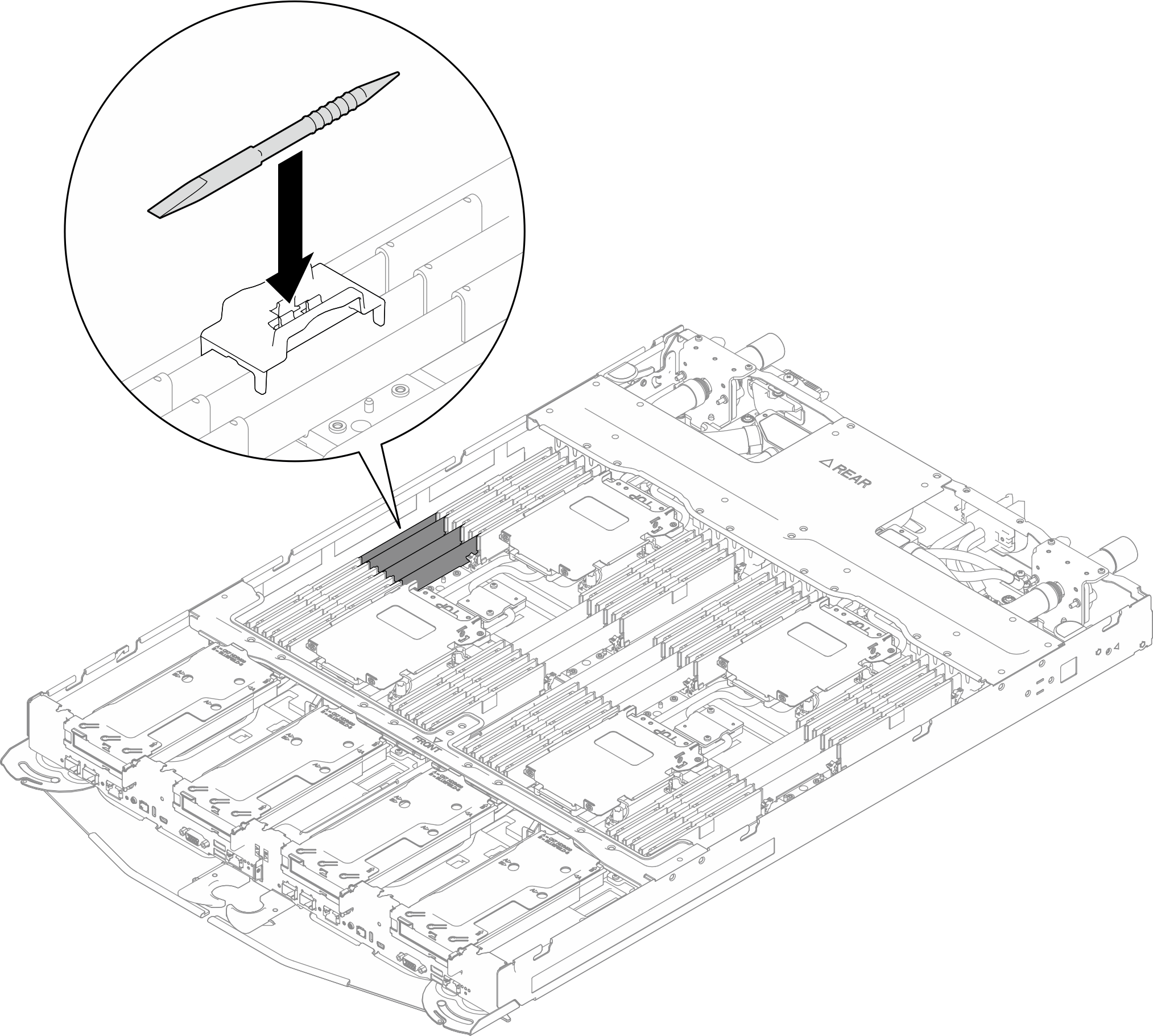
- Remove the memory module tool attached to the DIMM comb.NoteMemory module tool is recommended due to space limitations caused by location of water loop tubes through the memory section.Figure 2. Memory module tool removal
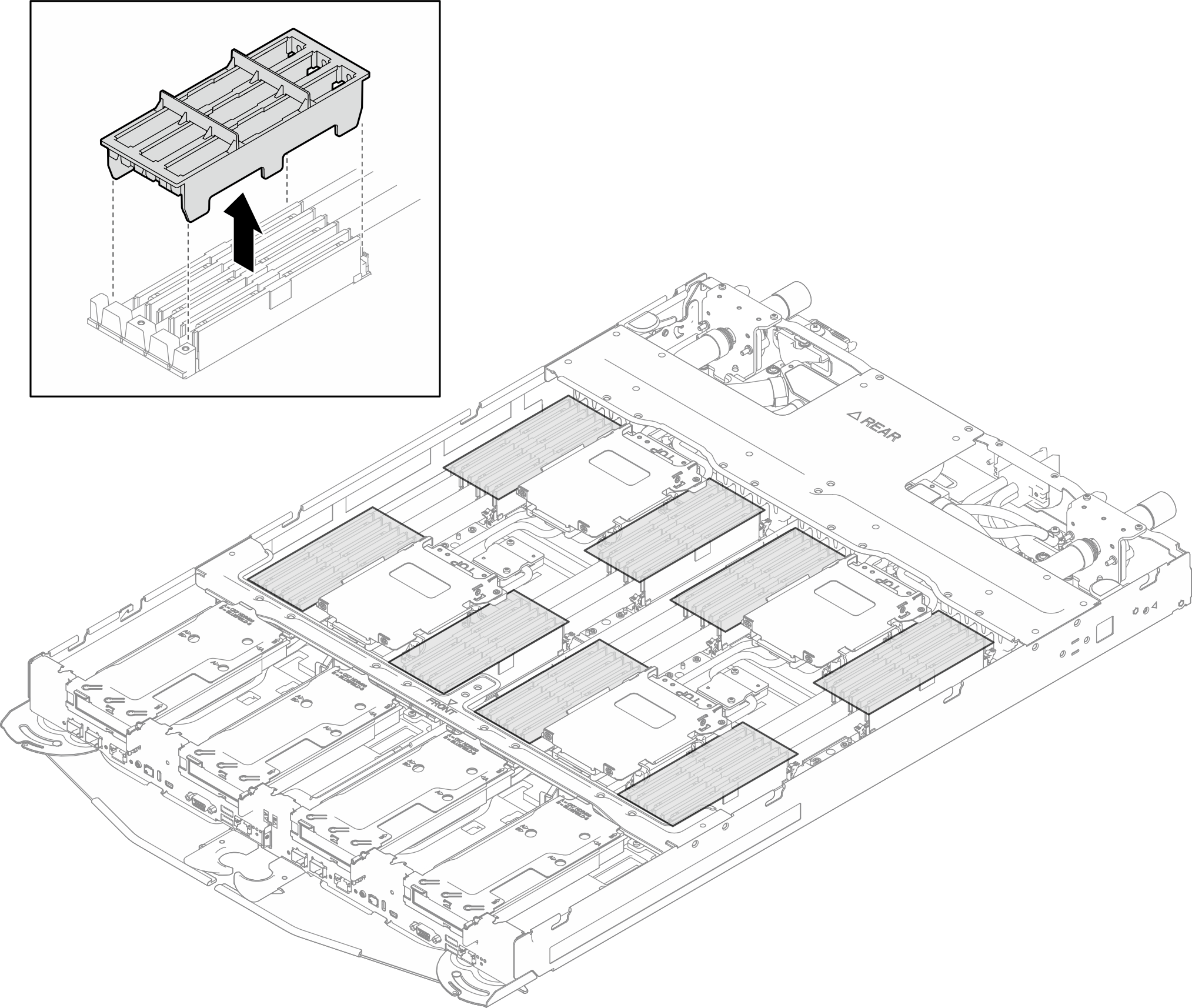
- Remove the DIMM cover. NoteDo not tilt the DIMM cover and keep it at an upright position to prevent damaging the gap pads.Figure 3. DIMM cover removal
- Unlock the retaining clips on each end of the memory module connector with the memory module tool.
 Place the tip of the tool on the top of the retaining clip.
 Press the tool to rotate and unlock the retaining clip.
Figure 4. Pressing retaining clips on memory module connector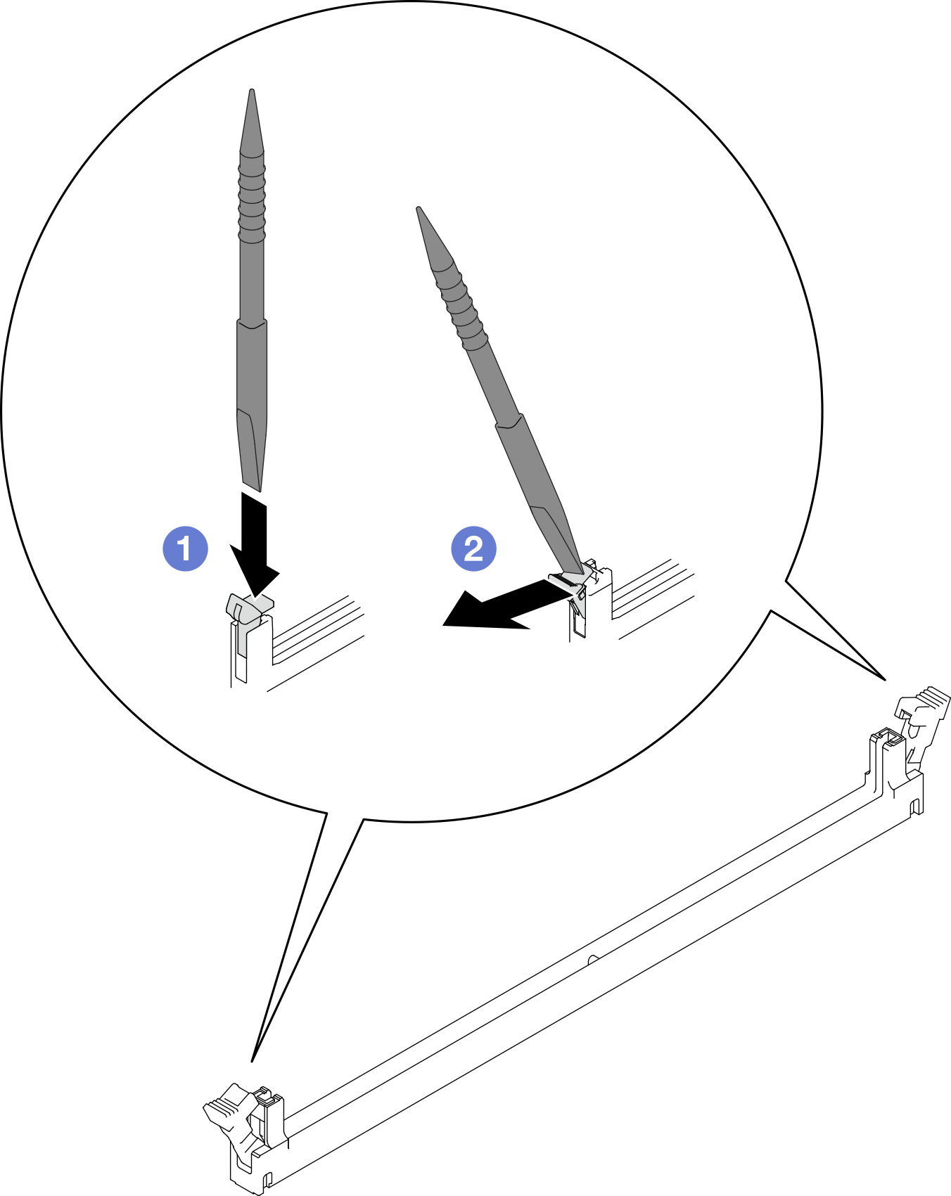 Attention
Memory modules are static-sensitive devices. The package must be grounded before it is opened.
To avoid breaking the retaining clips or damaging the memory module connectors, open and close the clips gently.
- Hold the right end and left end of the memory module at the same time. Keep the memory module in parallel with the connector; then, carefully remove the memory module.Figure 5. Memory module removal
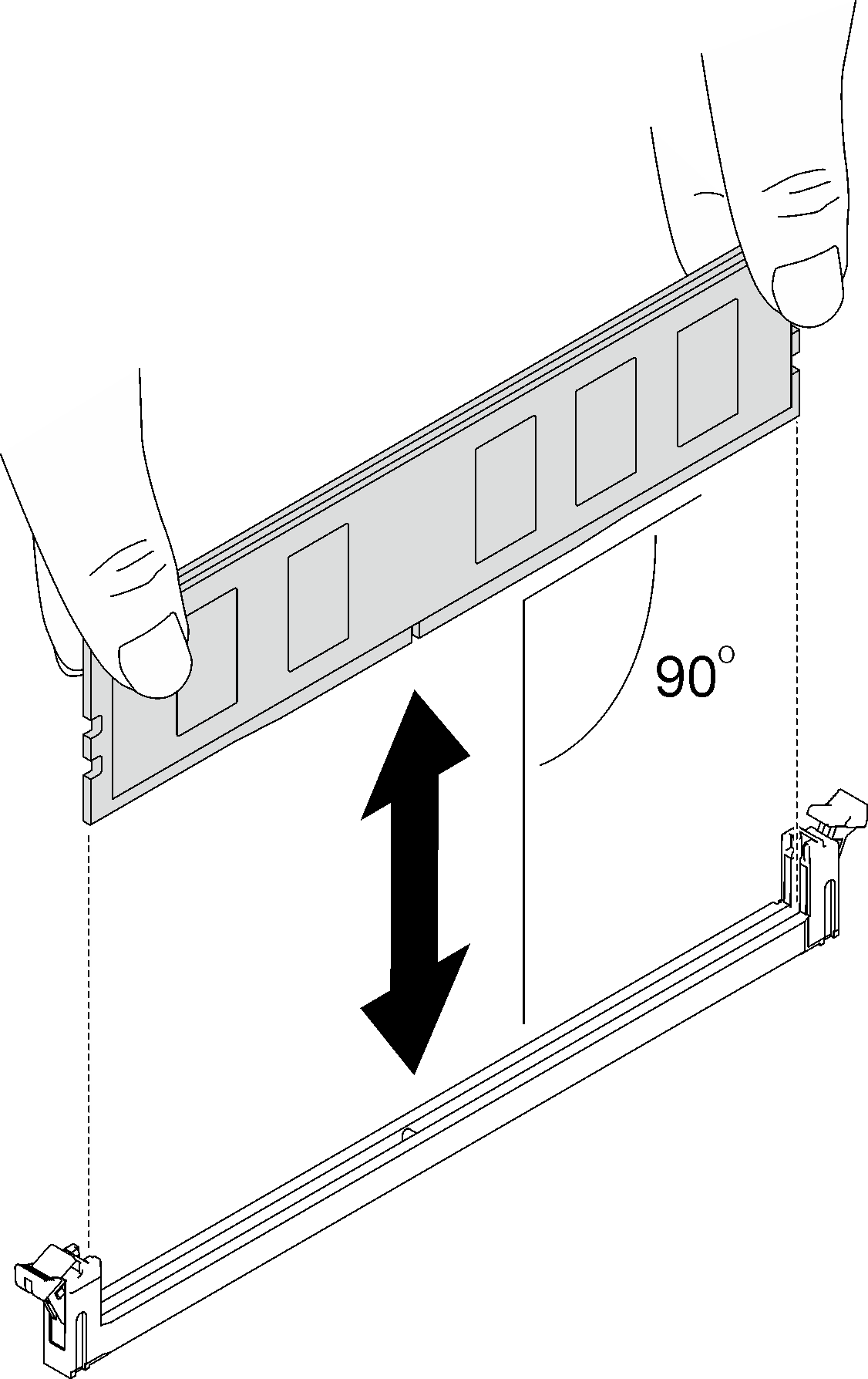 NoteMemory module should be in horizontal position during removal.
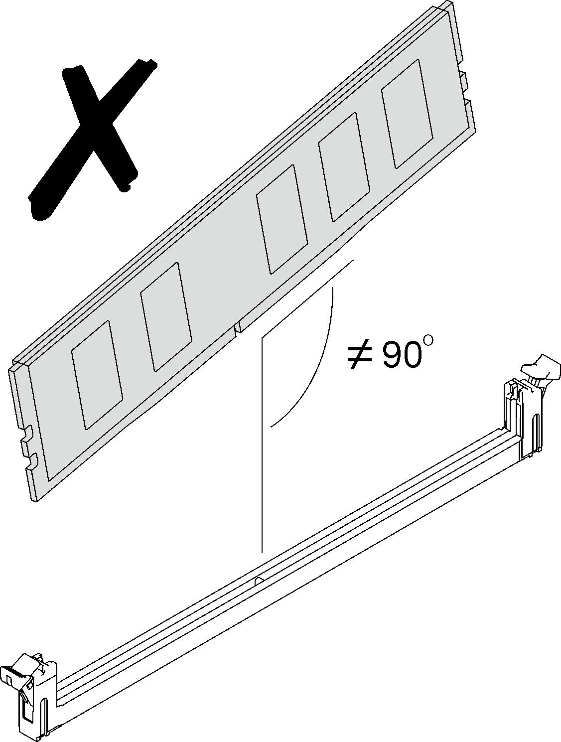
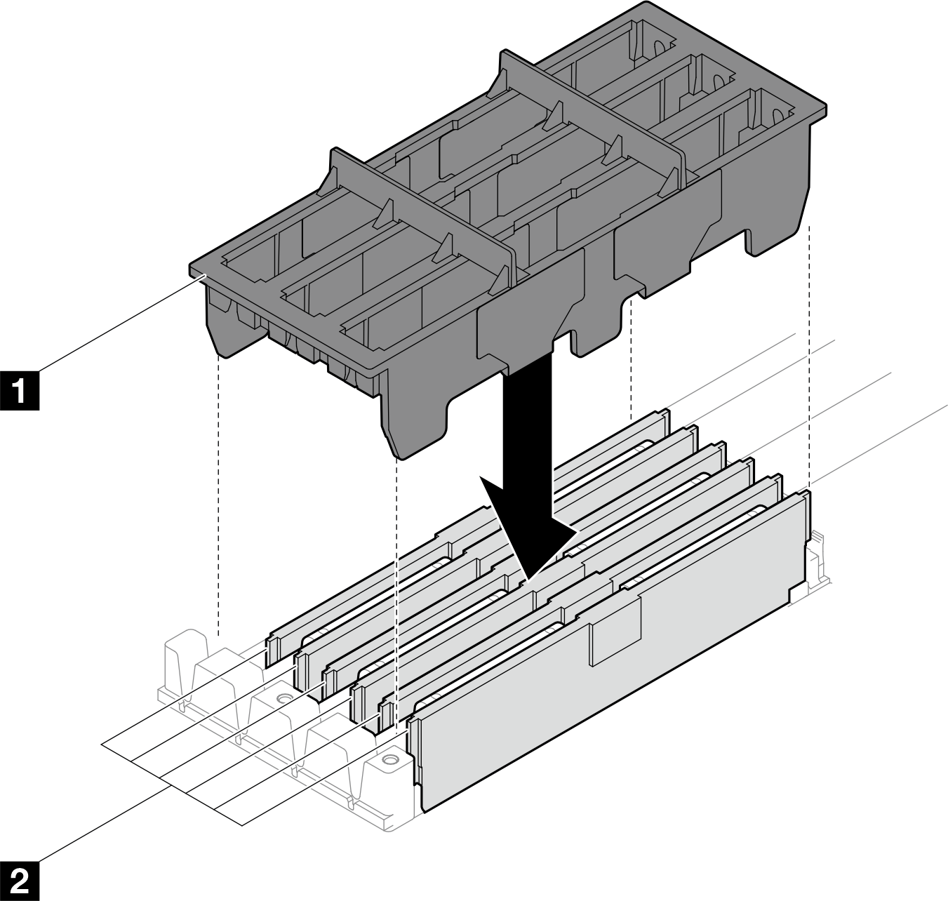
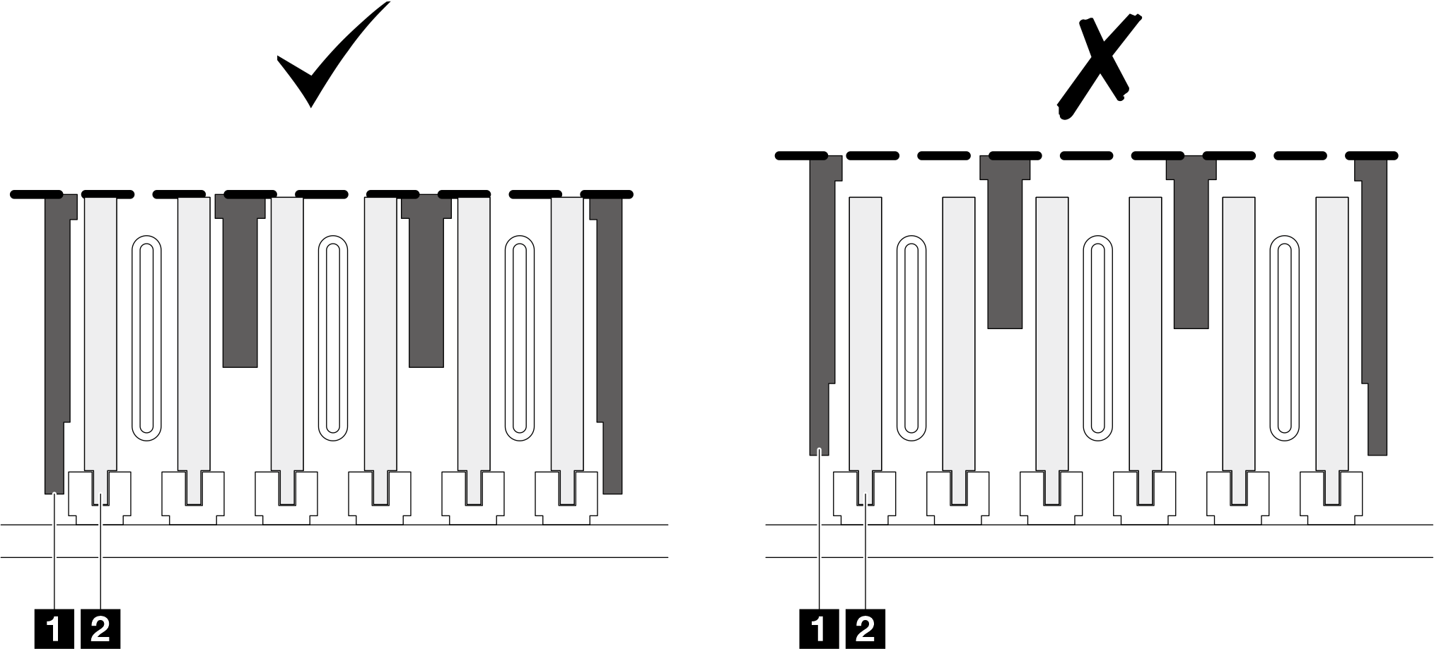
- Install the DIMM cover.Figure 6. Aligning center of DIMM cover and DIMMsNoteWhen installing the DIMM cover (1), the center of the DIMM cover should be aligned with the center of the DIMMs (2).
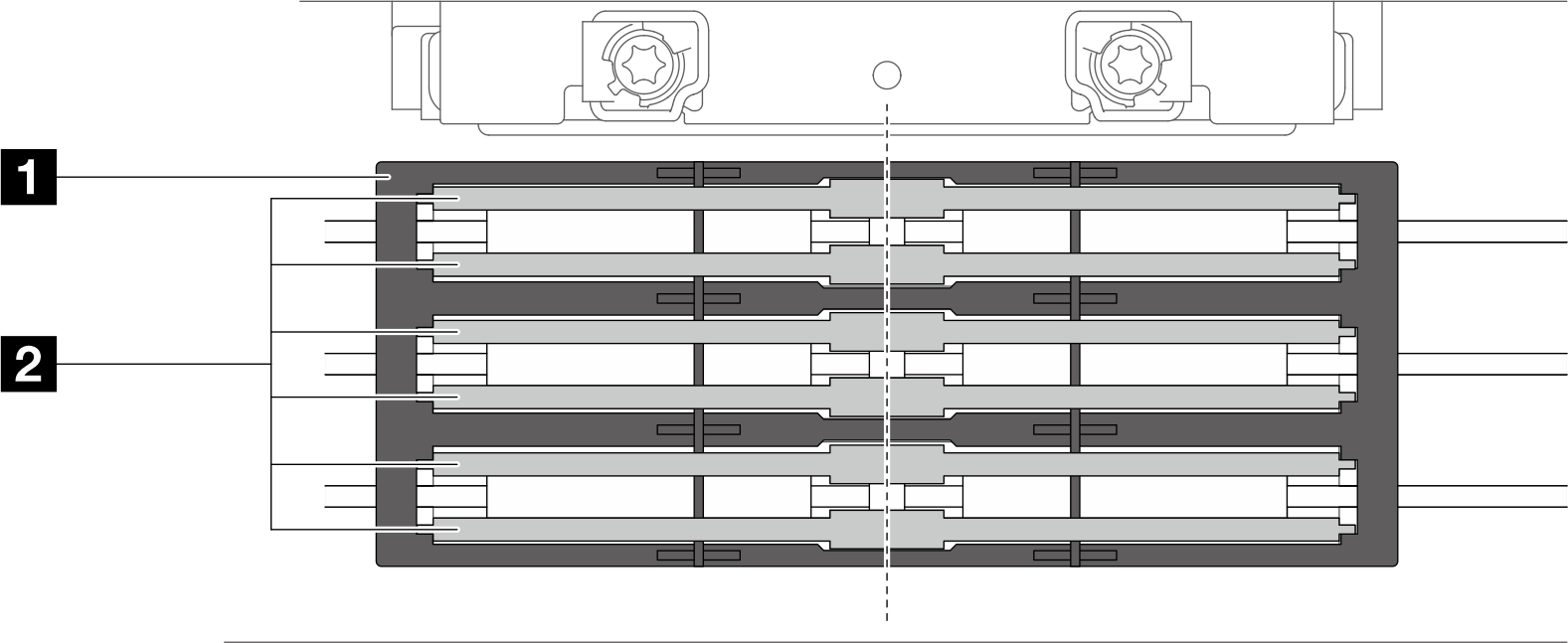 Figure 7. DIMM cover installationNoteDo not tilt the DIMM cover and keep it at an upright position to prevent damaging the gap pads.
 Figure 8. Check DIMM cover installation from DIMM slot side viewNoteCheck the side view of the DIMM slots and DIMM cover. Make sure the top of the DIMM cover is aligned with the top of the DIMMs. If the top of the DIMM cover is higher than the DIMMs, the DIMM cover is not correctly installed.
- 1 DIMM cover
- 2 DIMM
- Install the memory module tool to the DIMM comb.Figure 9. Memory module tool installation
- Install a memory module, see:
If you are instructed to return the component or optional device, follow all packaging instructions, and use any packaging materials for shipping that are supplied to you.