Node fan module and fan bridge cable routing
Follow the instructions in this section to learn how to do cable routing for fan module and fan bridge cable on the node.
Note
The protruding points between the cable slot are designed as the alignment points for the cable routing. Route the connector closer and face to the protruding point as illustrated so that the cable can be folded for easier cable routing.
Figure 1. Cable routing for fan module and fan bridge cable
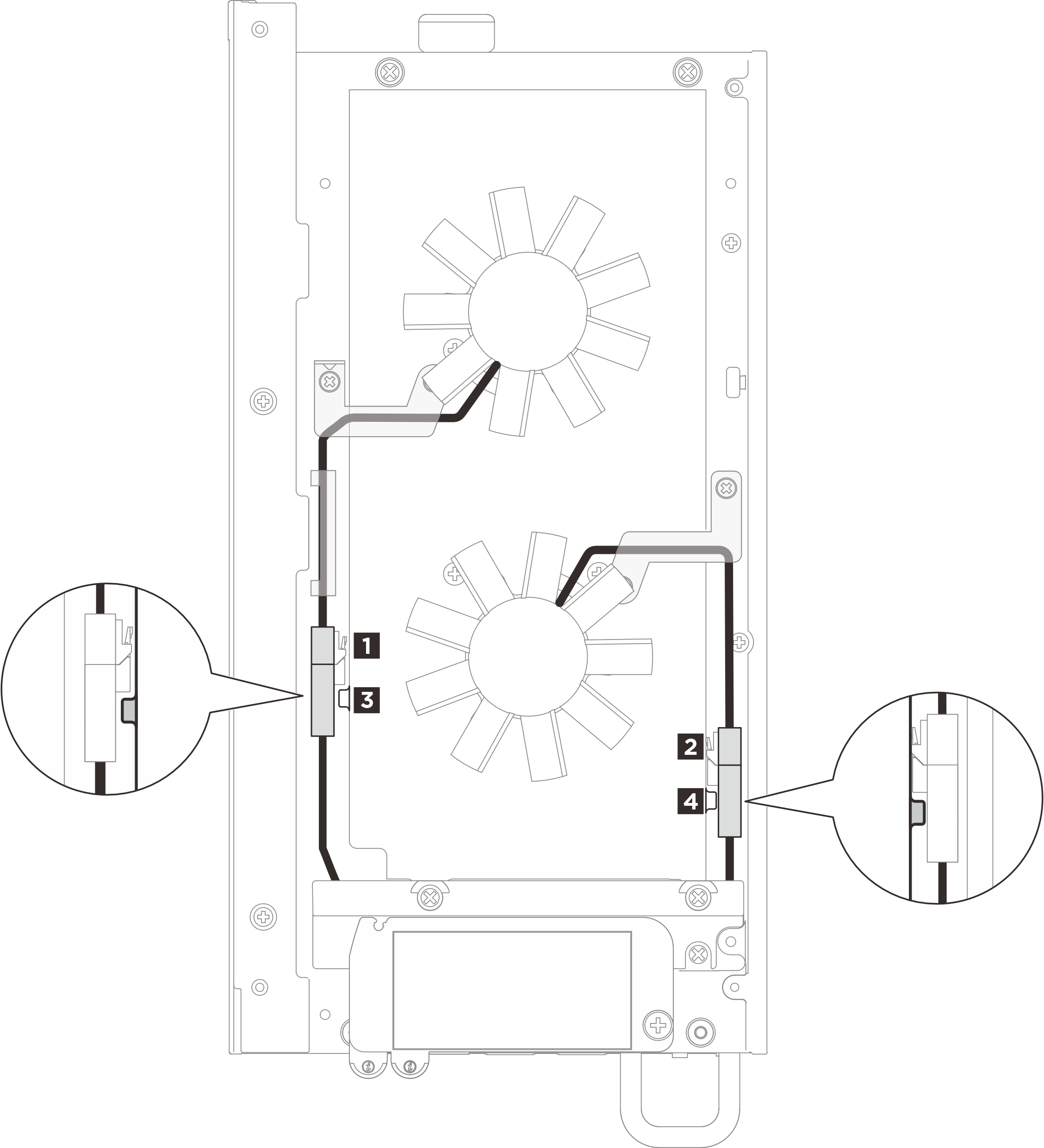
| Cable | From | To | Cable length |
| 1 | Fan module 1 | 3 Fan bridge cable 1 | 75 mm |
| 2 | Fan module 2 | 4 Fan bridge cable 2 | 75 mm |
Complete the following procedure to route the cables properly:
- There are labels attached on fan bridge cables and fan module cables. Before routing the cables, roll the label around the cable all the way through.Figure 2. Rolling label around the cable

- Press the cables with rolled labels into the cable slot on top cover as illustrated. Make sure the cable of Fan module 1 is secured between the foam and the chassis.Figure 3. Fan cable routing
 NoteMake sure to press the connectors into the slot to avoid interfering with the fan shroud.
Give documentation feedback