Install a node to the rack
Follow instructions in this section to install a node to the rack.
About this task
S002
CAUTION
The power-control button on the device and the power switch on the power supply do not turn off the electrical current supplied to the device. The device also might have more than one power cord. To remove all electrical current from the device, ensure that all power cords are disconnected from the power source.
R006

CAUTION
Do not place any object on top of a rack-mounted device unless that rack-mounted device is intended for use as a shelf.
Attention
Read Installation Guidelines and Safety inspection checklist to ensure that you work safely.
Power off the server and peripheral devices and disconnect the power cords and all external cables. See Power off the server.
Note
To install a node to an enclosure which is already on the rack, start from Install the node to the enclosure.
Install the enclosure to the rack
Procedure
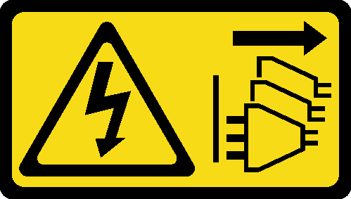
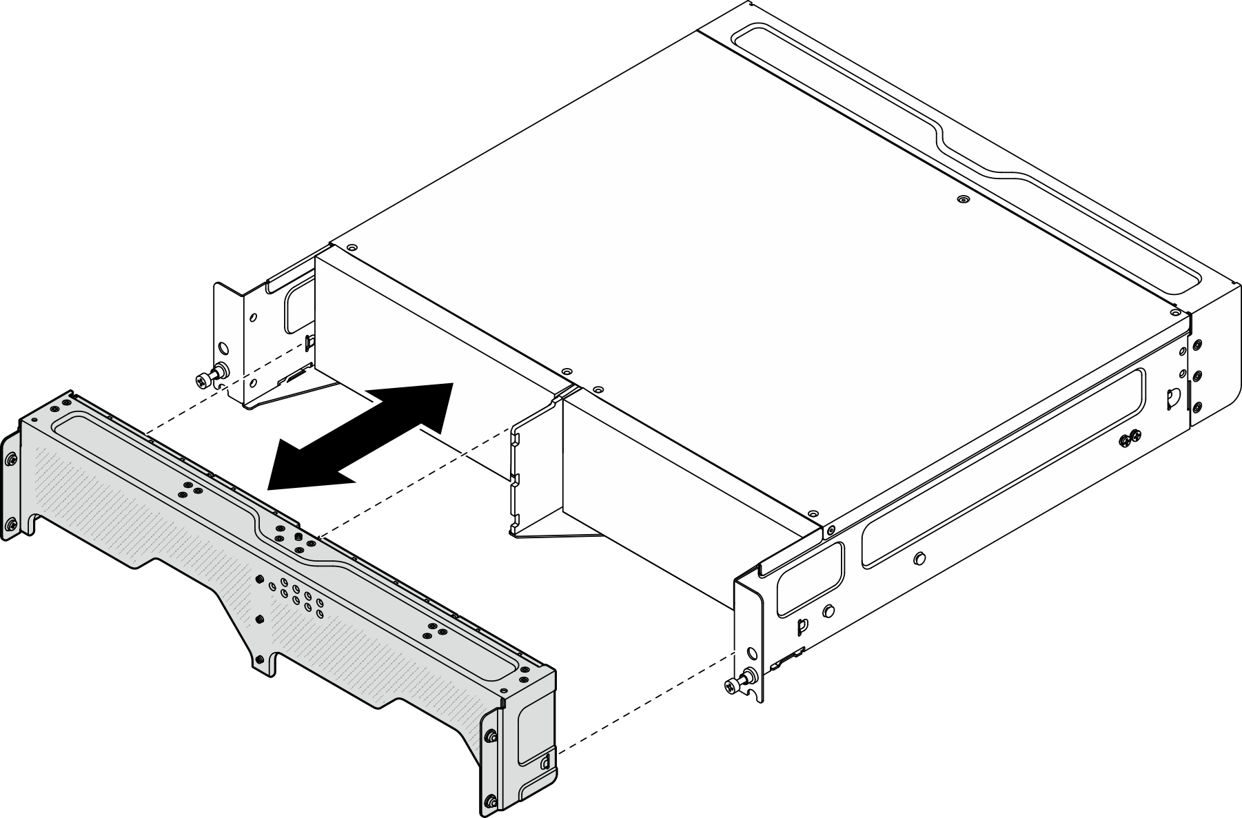
- If applicable, install the rear shipping bracket.
- Align the guide pins of the shipping bracket with the holes on the enclosure; then, push the shipping bracket toward the enclosure until it is firmly seated.Figure 1. Installing the shipping bracket
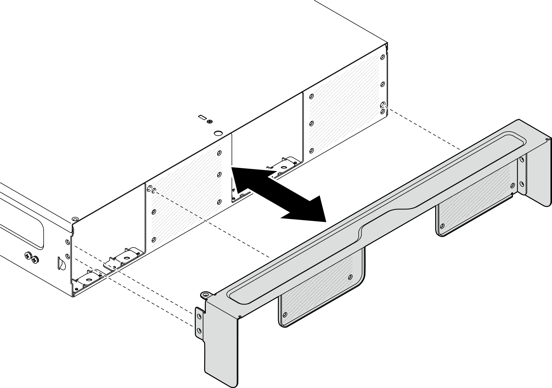
- Fasten fifteen screws to secure the shipping bracket.Figure 2. Fastening the screws
- Align the guide pins of the shipping bracket with the holes on the enclosure; then, push the shipping bracket toward the enclosure until it is firmly seated.
- Depending on the rail kit, remove the redundant screws from the enclosure.
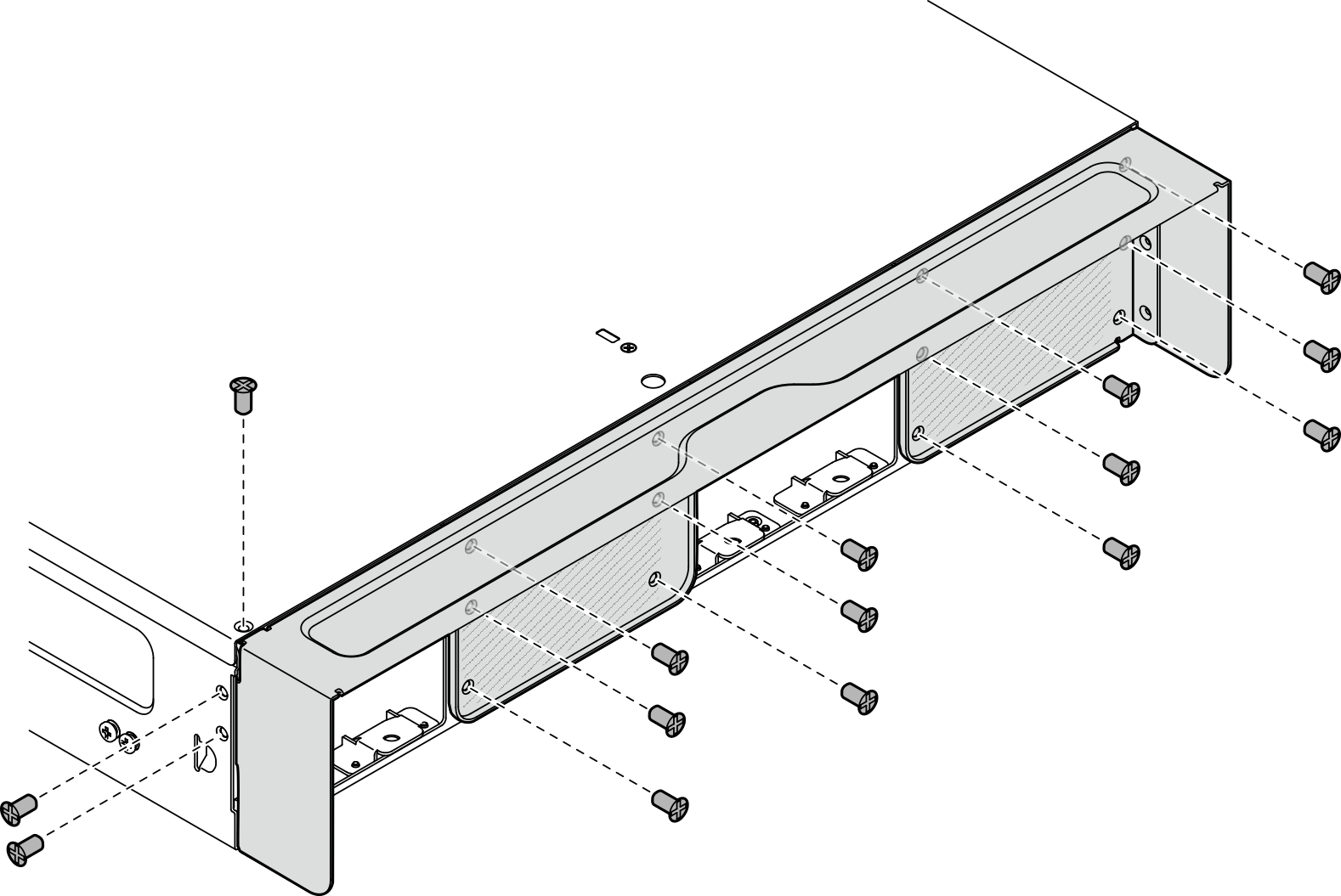
- To install the enclosure to ThinkEdge 600mm Ball Bearing Rail Kit, remove the middle one of the three screws; one for each side, total two screws should be removed.Figure 3. The screw on the enclosure to be removed
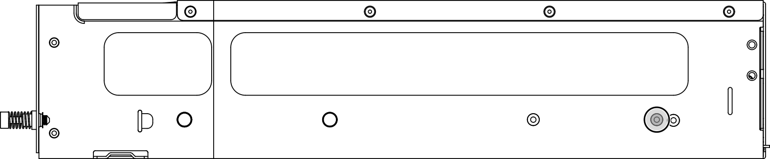
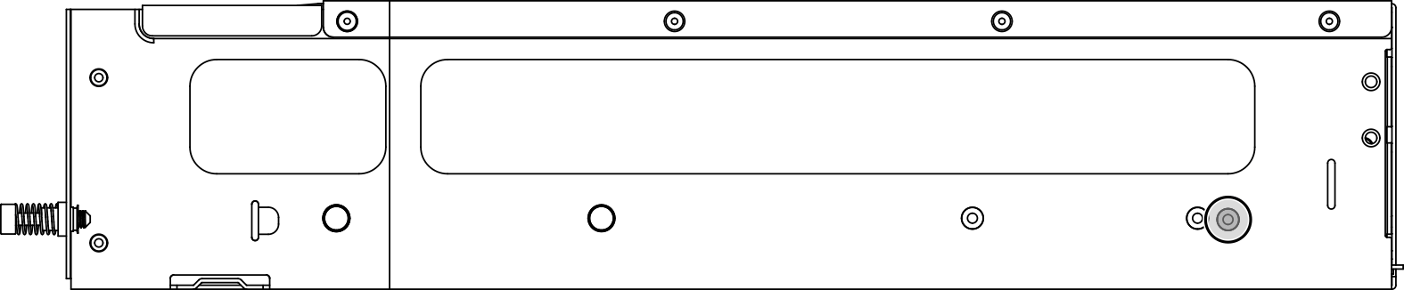
- To install the enclosure to the rail kit except for ThinkEdge 600mm Ball Bearing Rail Kit, remove the screw which is the closest to the rear of the enclosure; one for each side, total two screws should be removed.Figure 4. The screw on the enclosure to be removed
- To install the enclosure to ThinkEdge 600mm Ball Bearing Rail Kit, remove the middle one of the three screws; one for each side, total two screws should be removed.
- Install the inner rails to the enclosure.AttentionThere are “L” and “R” logos marked on the front of inner rails which represent the left rail and the right rail. Ensure correct rails are installed to the rack accordingly.
- Remove the two screws from the side of the enclosure; save the screws for later use.
- Align the mounting holes on the inner rail with the corresponding rail mounting pins on the side of the enclosure.
- Push the inner rail as shown until the mounting pins on the enclosure are locked in place.
- Tighten the two screws to secure the inner rail to the enclosure.
- Repeat this procedure to install the other inner rail.
Figure 5. Installing the inner rail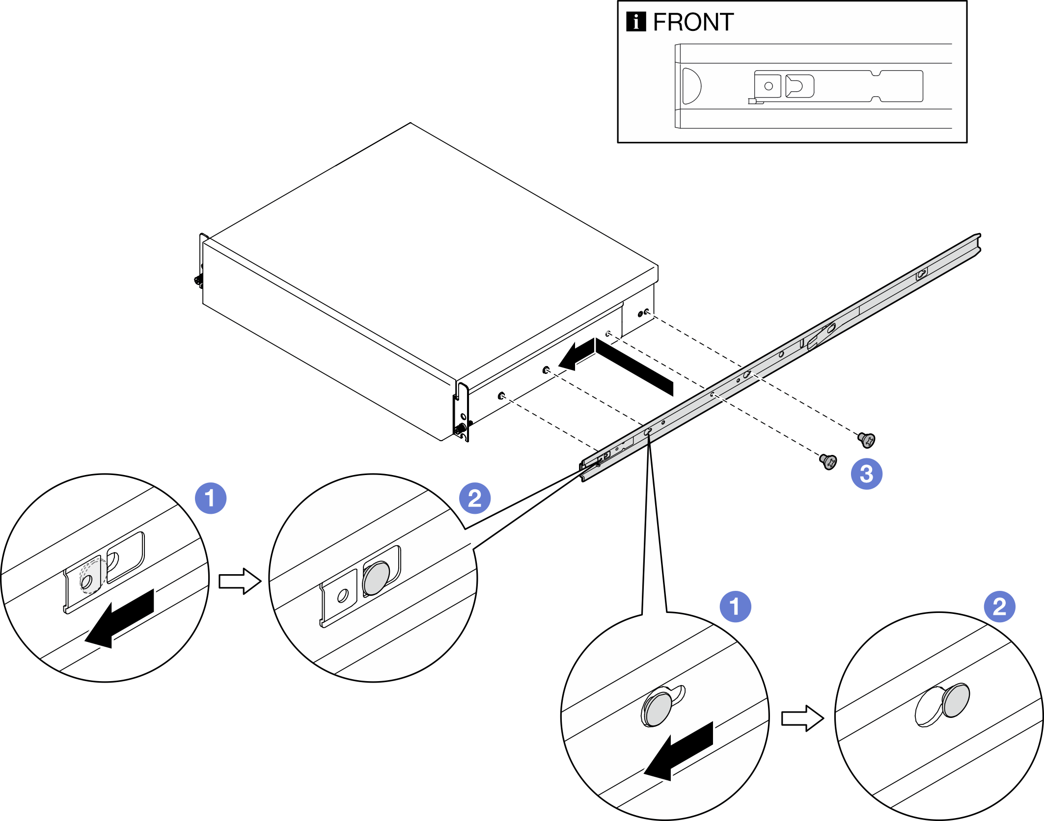
- Install the enclosure to the rack.
 Carefully lift the enclosure and align the enclosure with the rails on the rack; then, position the enclosure as shown and push it into the rack.
 Depending on the rail kit, press or lift the release latches.
 Push the enclosure all the way into the rack until the enclosure locks into place with a click.
Figure 6. Installing the enclosure to the rack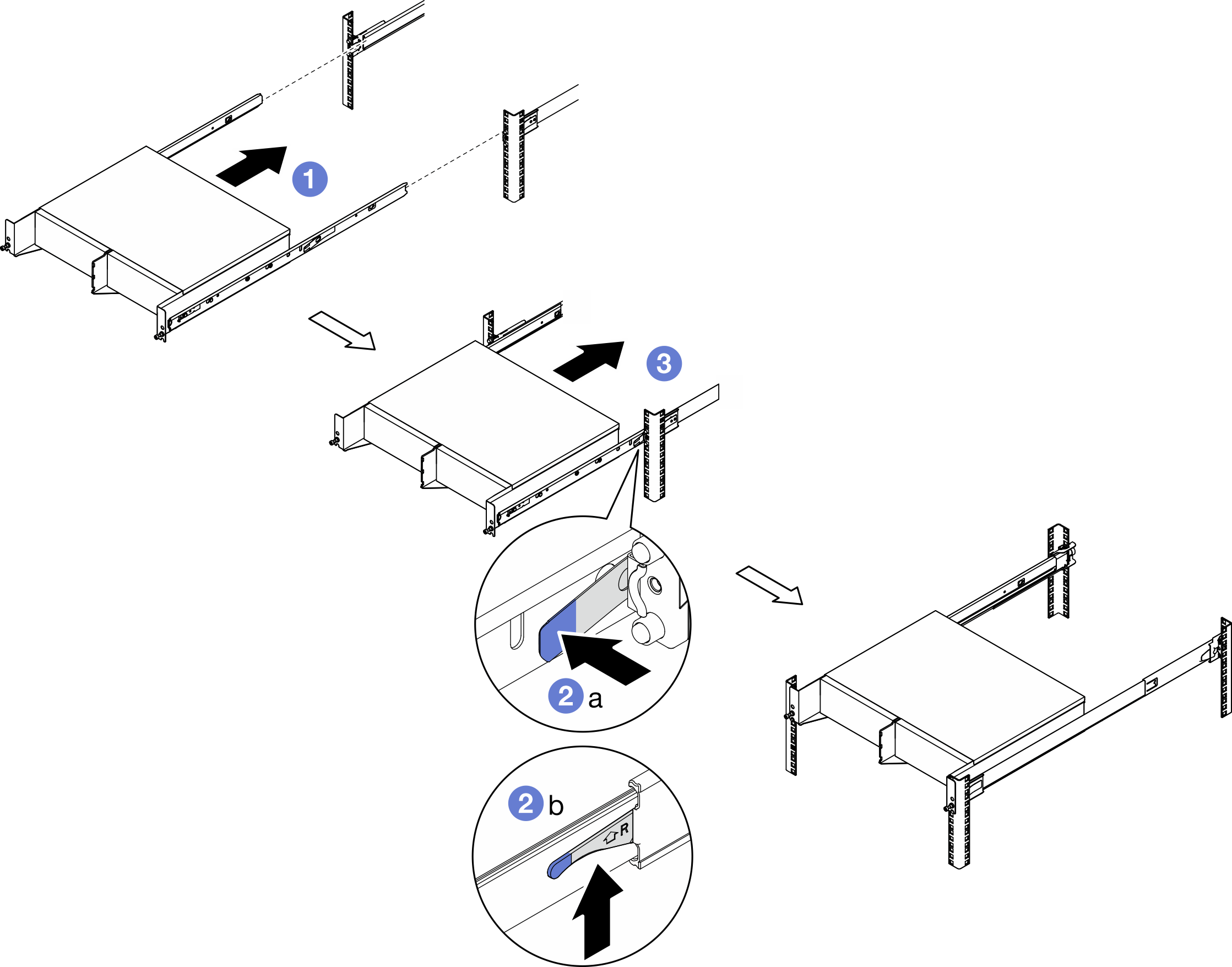
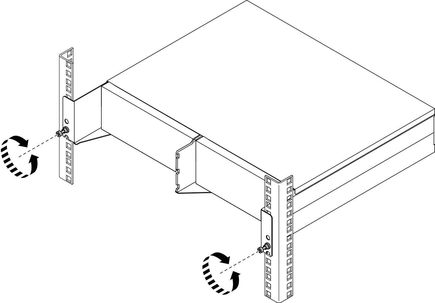
- Fasten the two thumb screws on the front of the enclosure to secure it to the rack.Figure 7. Securing the enclosure to the rack
Install the node to the enclosure
Procedure
- If the node comes with WLAN antennas, remove all the WLAN antennas.
- If applicable, turn the screw between the two SMA connectors clockwise to shorten the connectors into the chassis.NoteMake sure that the SMA connectors are shortened into the chassis; if the SMA connectors are extended and out of the chassis, the node can not be installed successfully.Figure 8. Shortening the SMA connectors
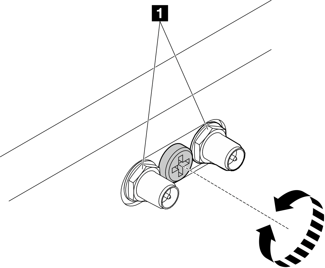
1 SMA connectors
- If applicable, turn the screw between the two SMA connectors clockwise to shorten the connectors into the chassis.
- Make sure that the enclosure bracket is installed to the node.
- Align the guide pins on the enclosure bracket to the rear of the node.
- Push the enclosure bracket to the node; then, secure the enclosure bracket with four screws.
Figure 9. Installing the enclosure bracket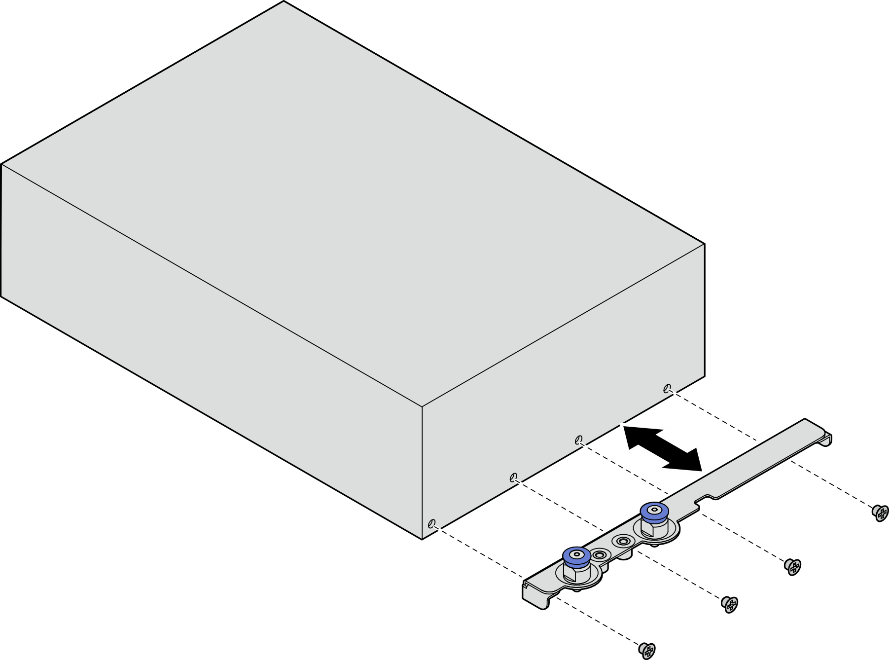
- If a node filler is installed in the node bay, remove it first.
- Loosen the two screws that secure the node filler.
- Remove the node filler from the node bay. Keep the node filler in a safe place for future use.
Figure 10. Removing the node filler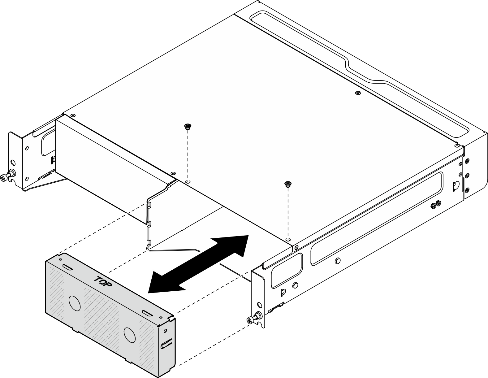
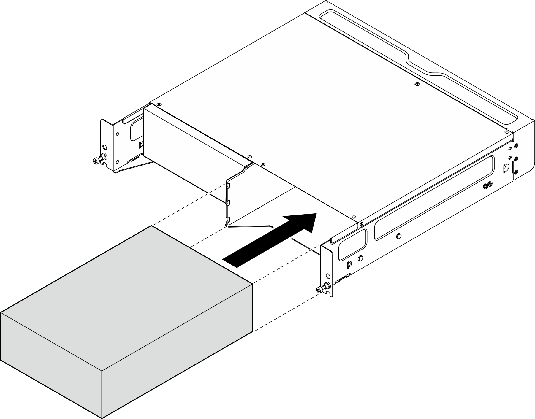
- Slide the node into the node bay until it clicks into place.Figure 11. Installing the node
- (Optional) If the enclosure is with only one node installed, install a node filler into the vacant node bay.
- Insert the node filler into the node bay.
- Secure the node filler with two screws.
Figure 12. Installing the node filler
Install the front shipping bracket
Attention
When the front shipping bracket is installed, the front operator panel is not accessible. Make sure to complete the following procedure before installing the front shipping bracket:
- Connect the power cable and other necessary external cables to the node.
- Power on the server and any peripheral devices. See Power on the server.
Procedure
- Push the shipping bracket toward the enclosure until it is firmly seated.Figure 13. Installing the shipping bracket
- Secure the captive screws of the shipping bracket.
- Fasten the captive screw on the top.
- Fasten the four captive screws on both sides.
- Fasten the three captive screws on the front.
Figure 14. Fastening the screws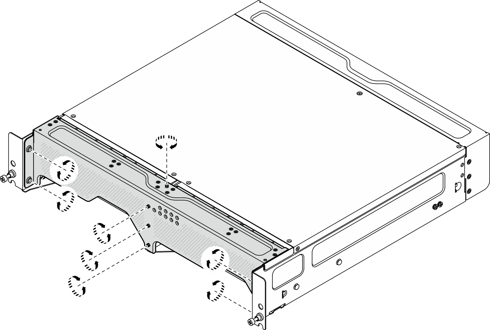
Give documentation feedback