Install a 2.5-inch drive backplane
Use this information to install a 2.5-inch drive backplane option.
Before you install a 2.5-inch drive backplane, complete the following steps:
Read Installation Guidelines to ensure that you work safely.
- Carefully lay the compute node on a flat, static-protective surface, orienting the compute node with the bezel pointing toward you.
Remove the compute node cover (see Remove the top cover).
Note
- Several different types of 2.5-inch drive backplanes can be installed in the compute node. For example, some 2.5-inch drive backplanes come with a lever, while others don’t (refer to the illustrations below). All are removed and installed in a similar manner.
- See the documentation that comes with an optional 2.5-inch drive backplane for device-specific information and information about installing other components that might be included as part of the option or about other components or modules that must be installed to use the option. For example, some optional 2.5-inch drive backplanes might require installation of a second processor.
To install a 2.5-inch drive backplane, complete the following steps:
Figure 1. 2.5-inch drive backplane installation
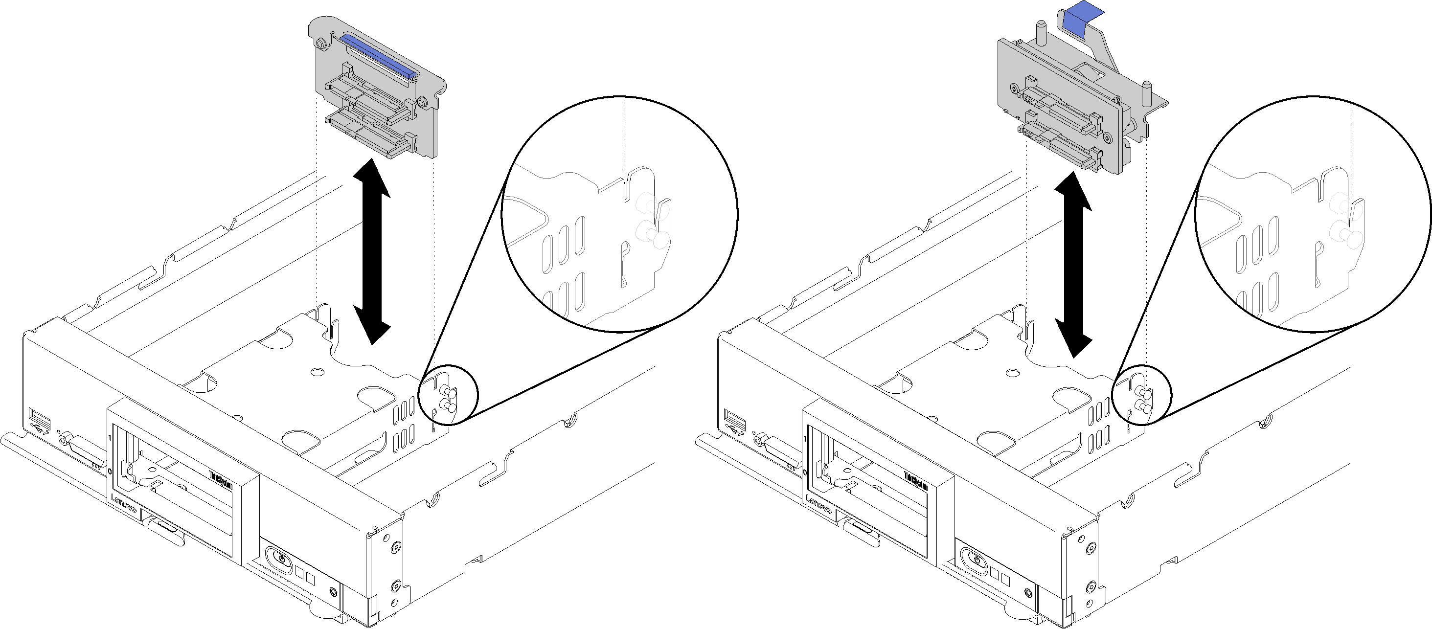
Align the backplane with the storage cage and the connector on the system board and press the backplane into position until it is fully seated in the connector.
Note
All 2.5-inch drive backplanes use the same connector on the system board; however, there are two alignment slots in the storage cage to accommodate different backplane types. Make sure that you align the backplane and system board connectors when inserting the backplane in the storage cage.
After you install the 2.5-inch drive backplane, complete the following steps:
- If the RAID adapter was removed, install it now. (see Install a RAID adapter).
- Install any removed storage drives and drive bay fillers (see Install a 2.5-inch hot-swap drive).NoteInstall storage drives in the same bay locations as from which they were removed.
Install the compute node cover (see Install the compute node cover ).
Install the compute node into the chassis (see Install the compute node in the chassis ).
Demo video
Give documentation feedback