This component can be installed as an optional device or as a CRU. The installation procedure is the same for the optional device and the CRU.
The optional Flex System PCIe Expansion Node supports additional PCIe adapters and I/O expansion adapters to provide a cost-effective way for you to increase and customize the capabilities of the compute node. For additional information, see PCIe Expansion Node.
Attention
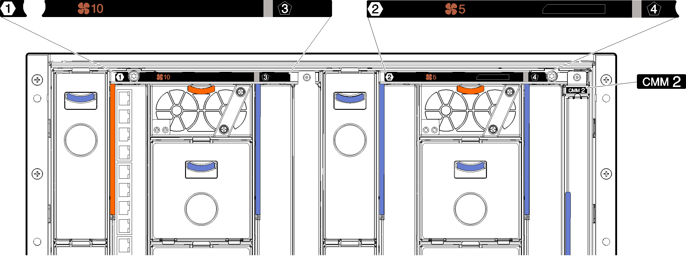
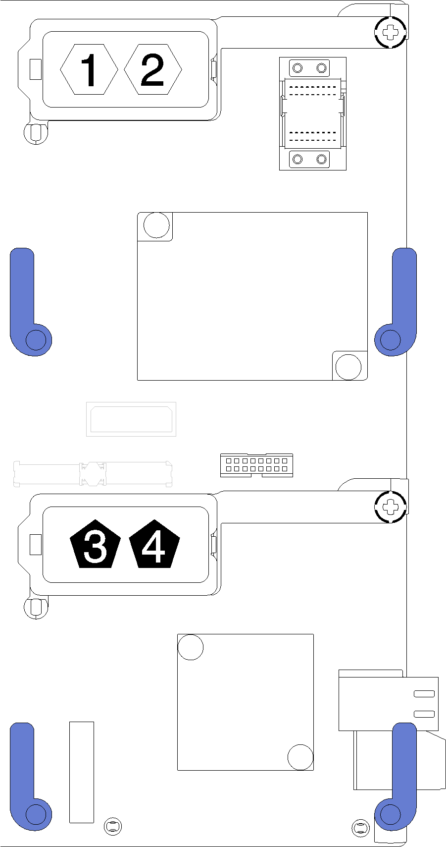
When installing an I/O adapter in one of the I/O expansion connectors, make sure the numbers in the Hexagon and Pentagon on the I/O expansion connector (see the service labeling on top of the compute node cover for details) corresponds to the particular shape and numbering of the I/O module bay on the Flex chassis (see the service labeling at the top on the rear of the chassis for details). If the correlation is incorrect, communication with the chassis may fail.
Figure 1. Service labeling on the rear of the chassis
Figure 2. Hexagon and Pentagon number location on the I/O expansion connector
To install an I/O expansion adapter, complete the following steps:
Watch the procedure. A video of the installation process is available:
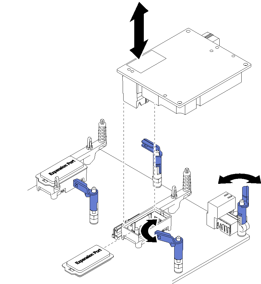
Remove the expansion cover from the connector, if one is present.
Touch the static-protective package that contains the expansion adapter to any unpainted metal surface on the Lenovo Flex System chassis or any unpainted metal surface on any other grounded rack component; then, remove the expansion adapter from the package.
Rotate the retention clips outward.
Orient the connector on the expansion adapter with the I/O expansion connector and alignment pins on the system board; then, press the adapter into the I/O expansion connector.
Firmly press on the indicated locations to seat the expansion adapter in the connector and over the alignment pins.
Close the retention clips to secure the adapter.
After you install the I/O expansion adapter, complete the following steps: