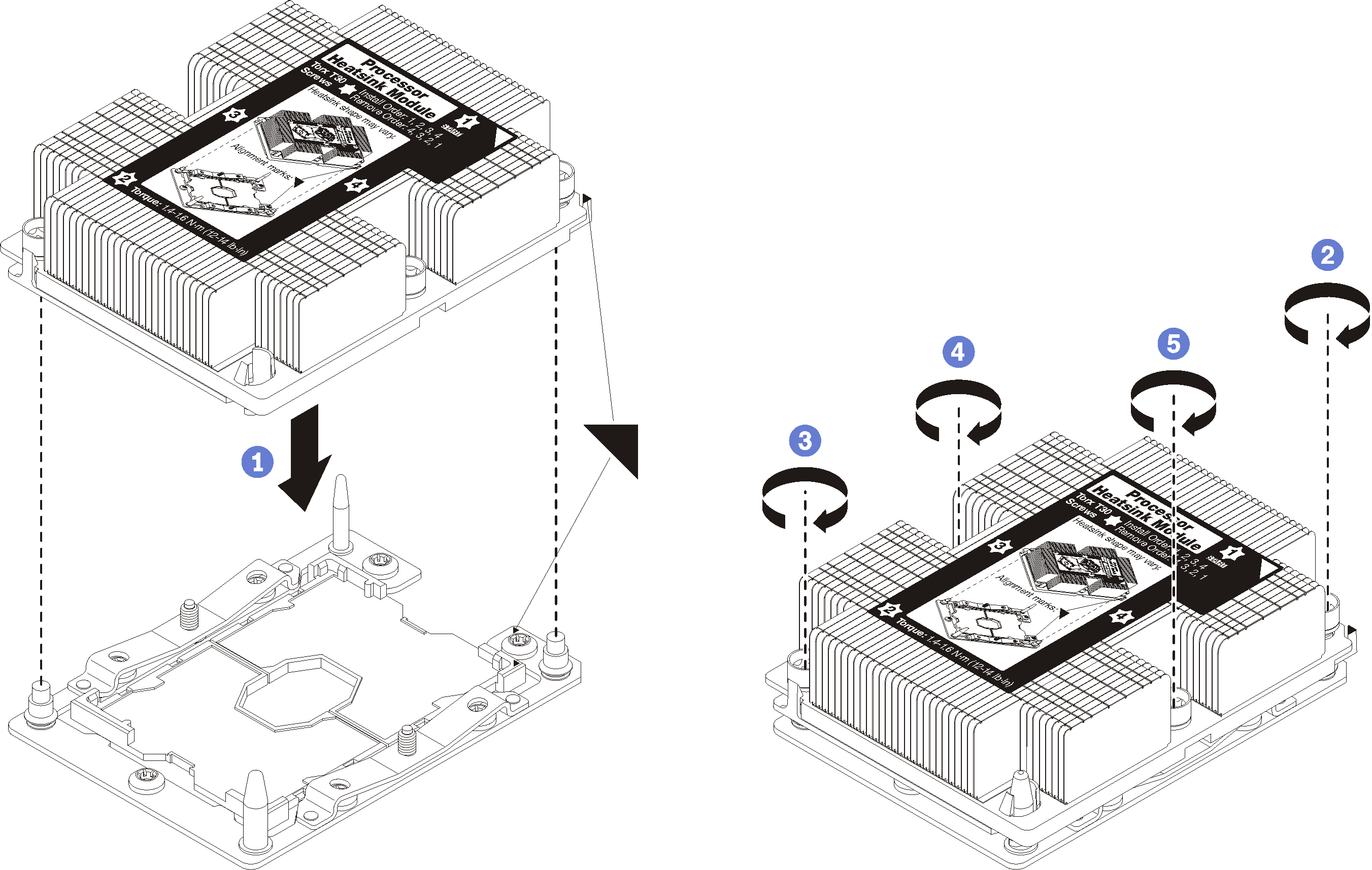
Install a processor-heat-sink module
The processor and heat sink are removed together as part of a processor-heat-sink-module (PHM) assembly. PHM installation requires a Torx T30 driver.
Each processor socket must always contain a PHM or a cover and heat sink baffle. When removing or installing a PHM, protect empty processor sockets with a cover.
Do not touch the processor socket or processor contacts. Processor-socket contacts are very fragile and easily damaged. Contaminants on the processor contacts, such as oil from your skin, can cause connection failures.
Remove and install only one PHM at a time. If the system board supports multiple processors, install the PHMs starting with the first processor socket.
Do not allow the thermal grease on the processor or heat sink to come in contact with anything. Contact with any surface can compromise the thermal grease, rendering it ineffective. Thermal grease can damage components, such as electrical connectors in the processor socket. Do not remove the grease cover from a heat sink until you are instructed to do so.
To ensure the best performance, check the manufacturing date on the new heat sink and make sure it does not exceed two years. Otherwise, wipe off the existing thermal grease and apply the new grease onto it for optimal thermal performance.
PHMs are keyed for the socket where they can be installed and for their orientation in the socket.
See Lenovo ServerProven website for a list of processors supported for your compute node. All processors on the system board must have the same speed, number of cores, and frequency.
Before you install a new PHM or replacement processor, update your system firmware to the latest level. See Update the firmware.
Installing an additional PHM can change the memory requirements for your system. See Install a memory module for a list of processor-to-memory relationships.
The maximal capacity the system supports varies with the processor(s) installed:
L processors (model name ending with L): 4.5 TB
M processors (model name ending with M): 2 TB
Other processors that support PMM: 1 TB
When using Intel Xeon Gold 6126T 12C 125W 2.6 GHz Processor, Intel Xeon Gold 6144 8C 150W 3.5 GHz Processor, Intel Xeon Gold 6146 12C 165W 3.2 GHz Processor, Intel Xeon Platinum 8160T 24C 150W 2.1 GHz Processor, or Intel Xeon Platinum 6244 8C 150W 3.6 GHz Processor, please note the following:
The ambient temperature should be less than 30°C.
When operating above 30°C or in the event of a fan failure, the server will continue to function as long as all the component’s temperature requirements are met. However, the performance may be reduced.
The noise level will be significantly higher than the base models.
Read Installation Guidelines to ensure that you work safely.
- Carefully lay the compute node on a flat, static-protective surface, orienting the compute node with the bezel pointing toward you.
Remove the compute node cover (see Remove the top cover).
Remove the air baffle. See Remove the air baffle.
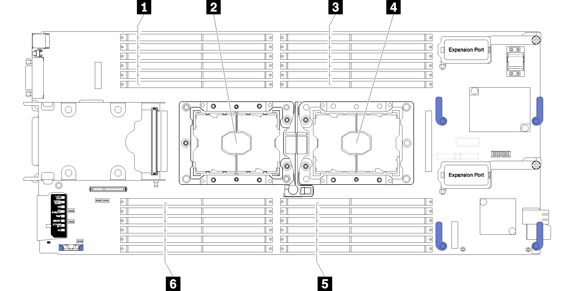
| 1 DIMM connectors 13-18 | 4 Processor socket 1 |
| 2 Processor socket 2 | 5 DIMM connectors 7-12 |
| 3 DIMM connectors 1-6 | 6 DIMM connectors 19-24 |
Complete the following steps to install a PHM.
- Install the processor-heat-sink module on the system board.Figure 2. Installing a PHM
Install the air baffle (see Install the air baffle).
Install the compute node cover (see Install the compute node cover ).
Install the compute node into the chassis (see Install the compute node in the chassis ).
Demo video