4 x 2.5'' NVMe backplane
Use this section to understand the NVMe backplane cable routing for server model with four 2.5-inch front drives and one or two processors.
To connect cables for the front adapter assembly, refer to Front adapter assembly.
Cable routing for onboard configuration with one processor
Figure 1. Cable routing for onboard configuration of 4 x 2.5-inch front NVMe drives
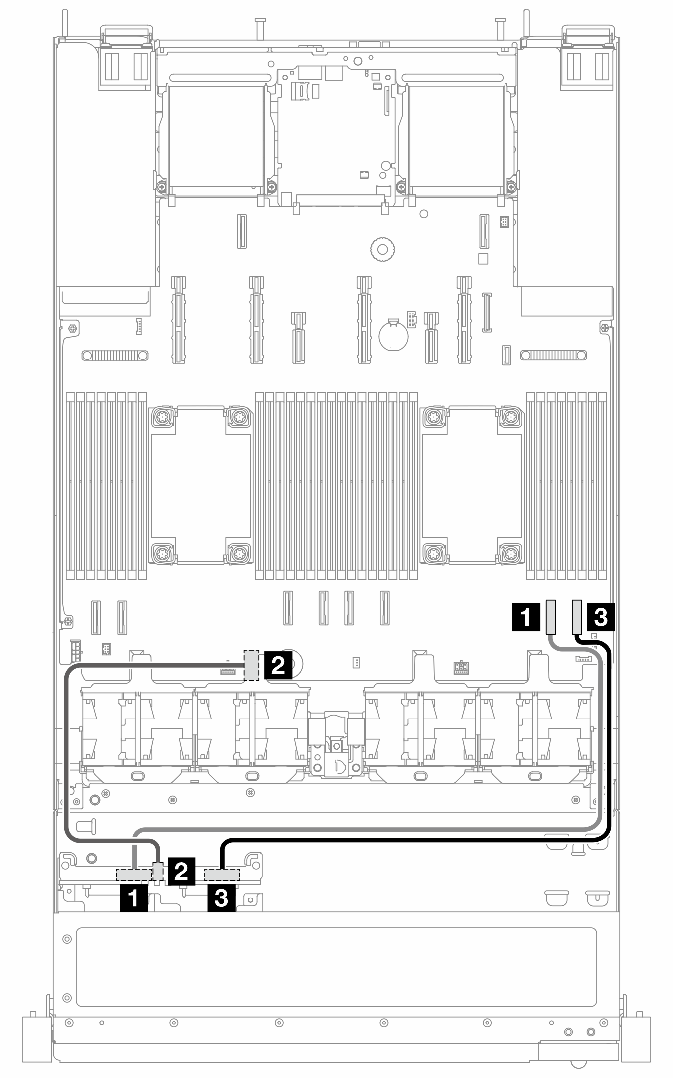
| From | To |
|---|---|
| 1 NVMe 0–1 | 1 PCIe 2 |
| 2 Power | 2 Power connector 2_A |
| 3 NVMe 2–3 | 3 PCIe 1 |
Cable routing for onboard configuration with two processors
Figure 2. Cable routing for onboard configuration of 4 x 2.5-inch front NVMe drives
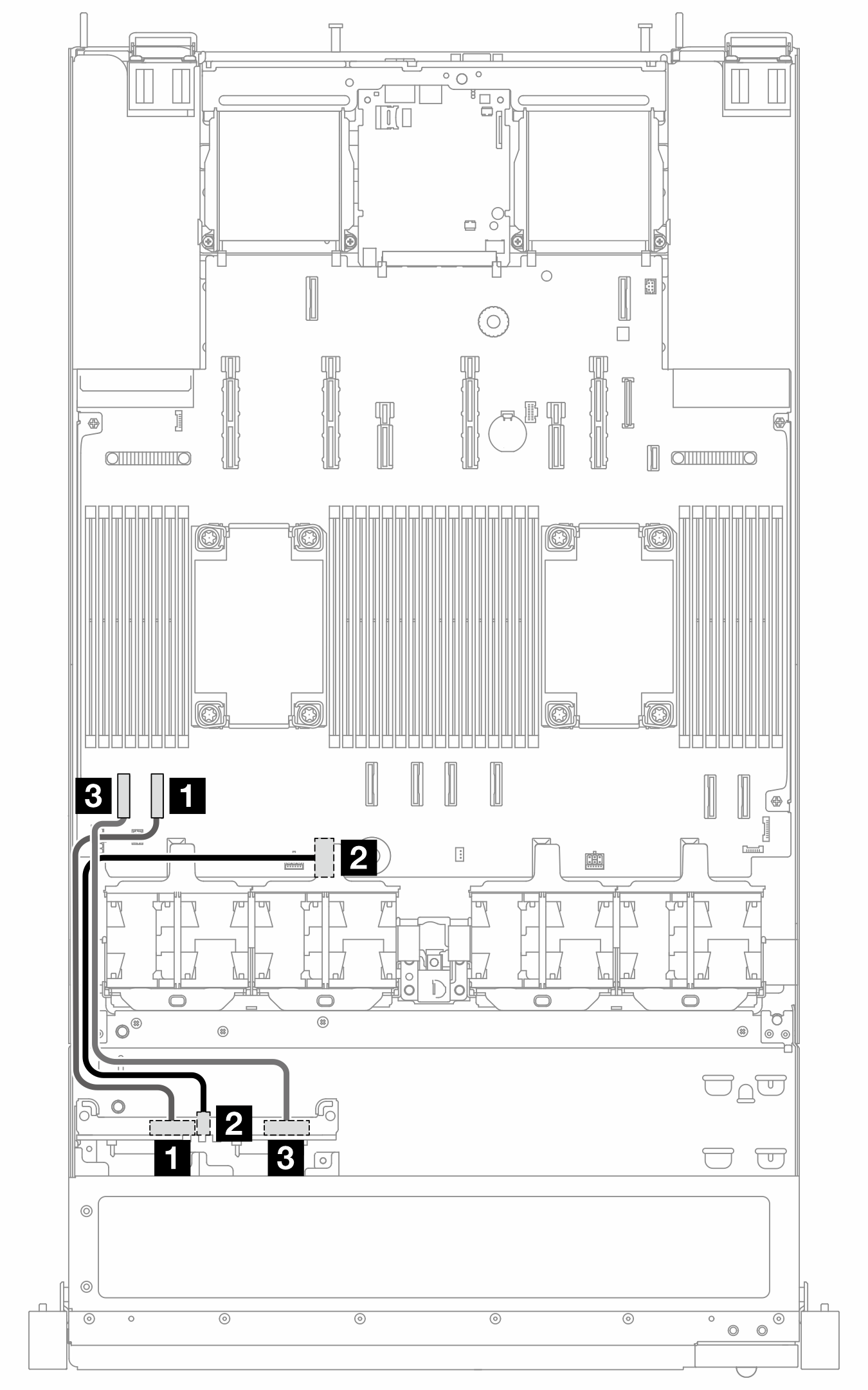
| From | To |
|---|---|
| 1 NVMe 0–1 | 1 PCIe 7 |
| 2 Power | 2 Power connector 2_A |
| 3 NVMe 2–3 | 3 PCIe 8 |
Give documentation feedback