CFF RAID adapter
Use the section to understand the power cable and signal input cable routing for CFF RAID adapters.
Cable routing for CFF RAID adapters
For the locations of connectors on CFF RAID adapters and the processor board, see RAID and HBA adapter connectors and System-board-assembly connectors for cable routing for details.
Cable routing for Gen 4 CFF RAID adapters
Figure 1. Gen 4 CFF RAID adapter cabling with two processors installed 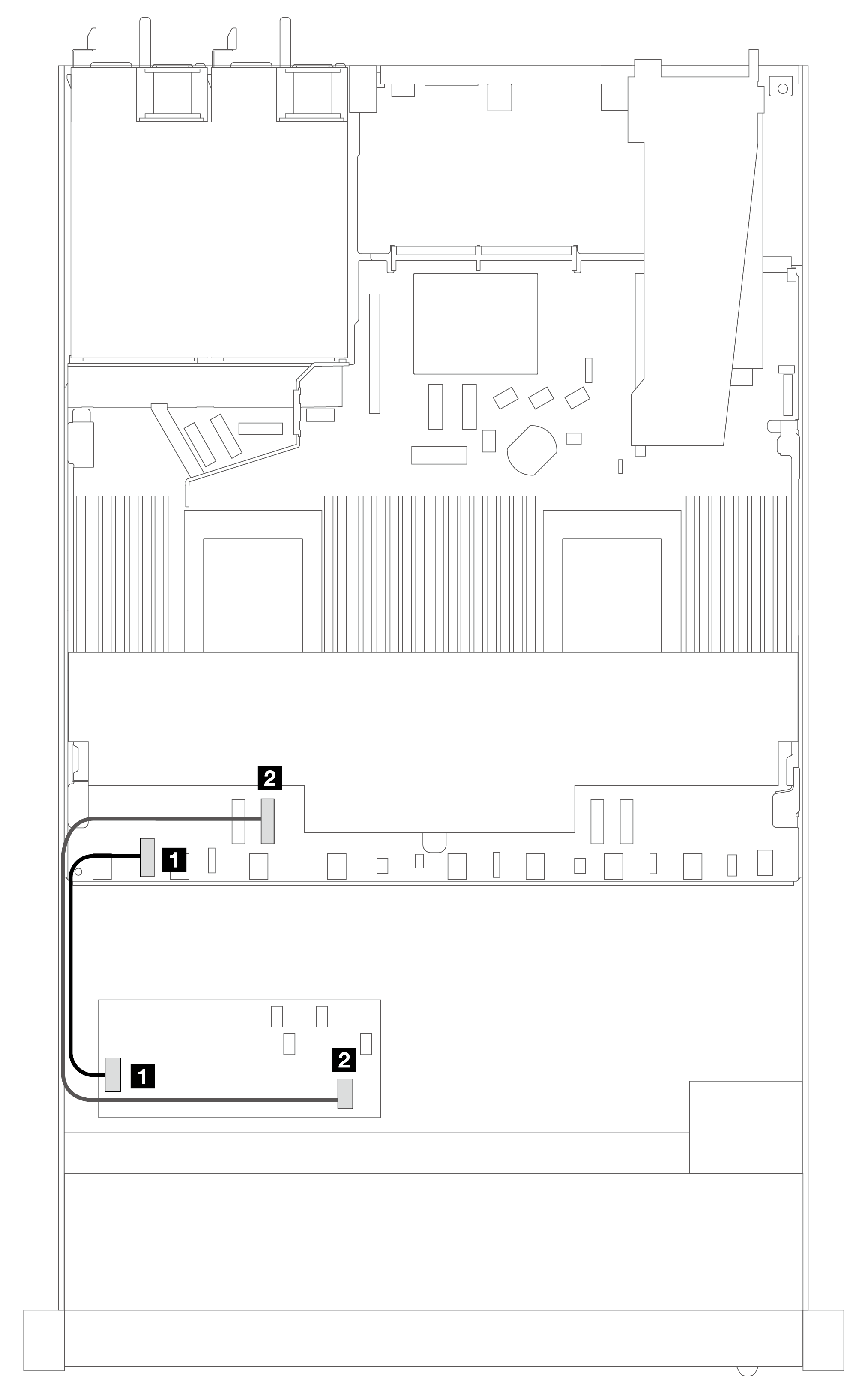 | Figure 2. Gen 4 CFF RAID adapter cabling with one processor installed 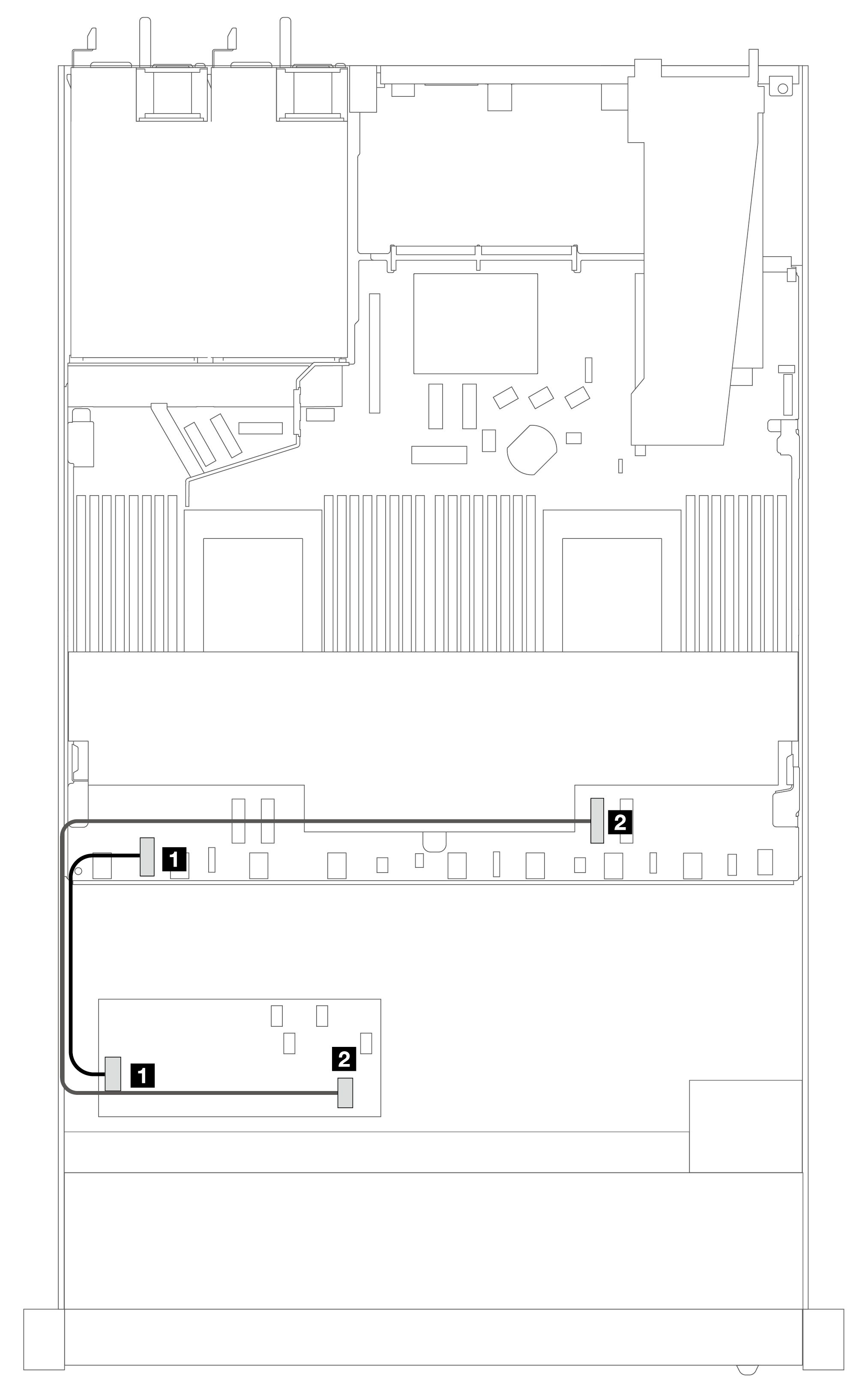 | ||
| From | To | From | To |
| 1 Power | 1 Internal RAID power connector | 1 Power | 1 Internal RAID power connector |
| 2 MB input | 2 PCIe 3 | 2 MB input | 2 PCIe 2 |
Cable routing for Gen 3 CFF RAID adapters
Figure 3. Gen 3 CFF RAID adapter cabling with two processors installed 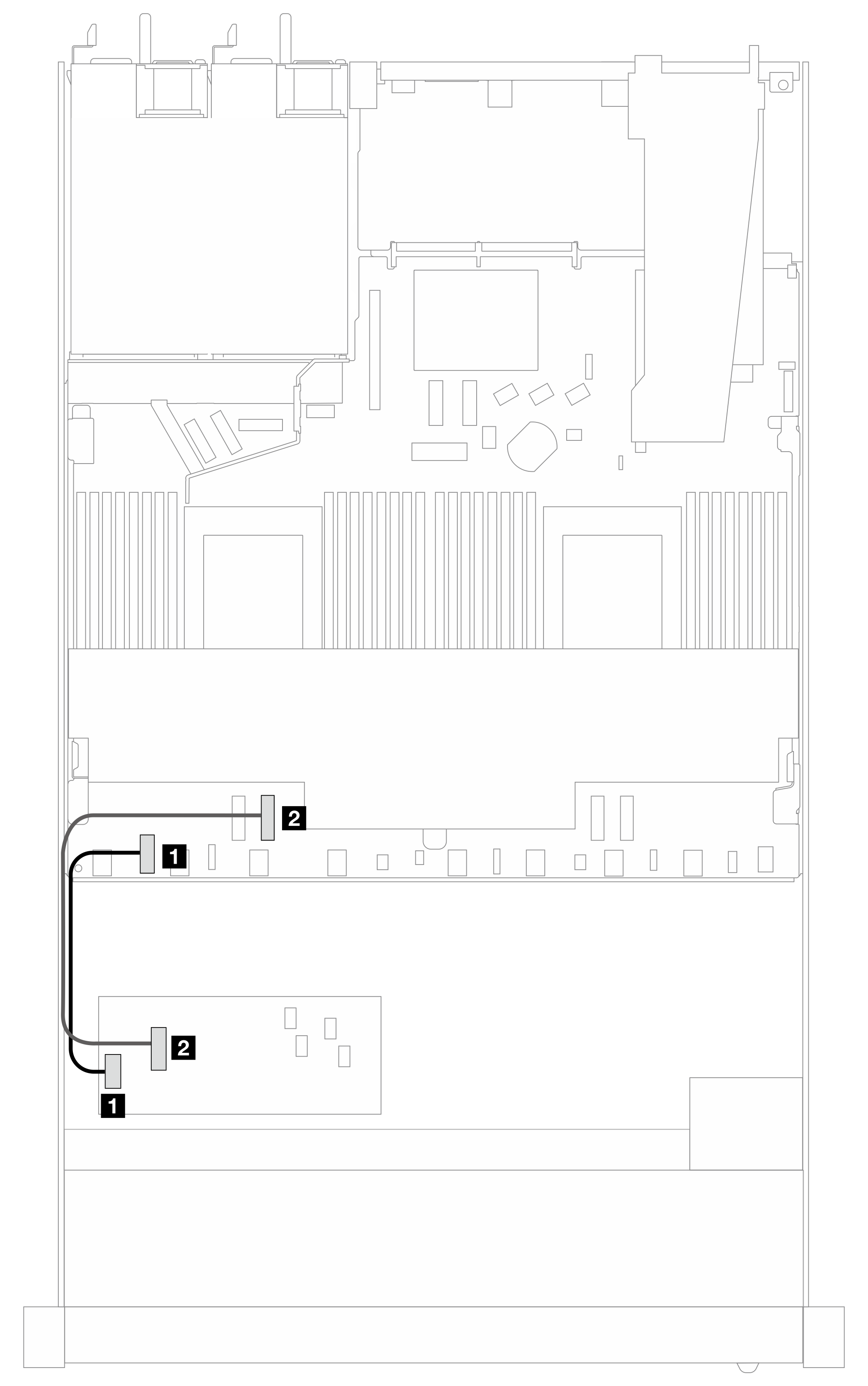 | Figure 4. Gen 3 CFF RAID adapter cabling with one processor installed 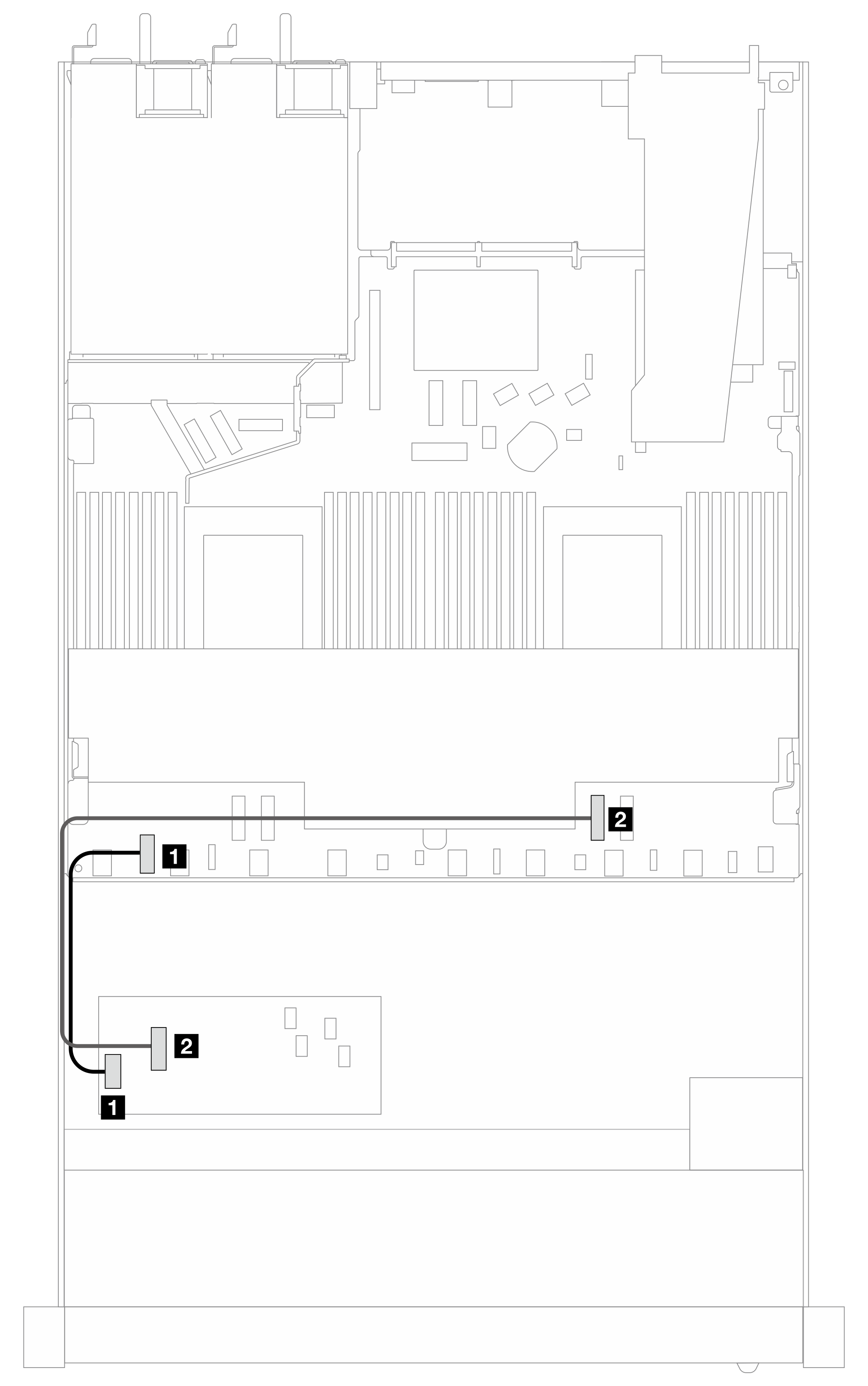 | ||
| From | To | From | To |
| 1 Power | 1 Internal RAID power connector | 1 Power | 1 Internal RAID power connector |
| 2 MB input | 2 PCIe 3 | 2 MB input | 2 PCIe 2 |
Note
When the server is installed with 4 x 2.5'' NVMe drives with two processors, the “MB input” connector on the CFF RAID adapters connects to PCIe 2 on the processor board.
Give documentation feedback