10 x 2.5'' NVMe (two processors)
See this section to understand the cable routing of 10 front NVMe drives with 10 x 2.5'' AnyBay backplane installed.
Figure 1. Cable routing for onboard configuration of 10 x 2.5'' NVMe front drives
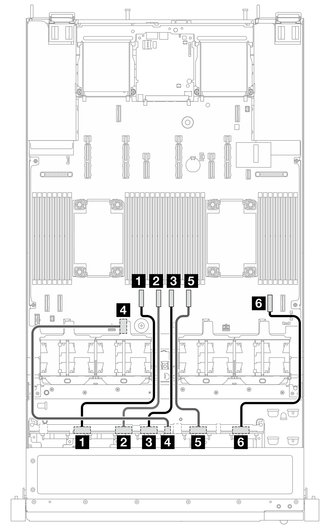
| From | To | Cable length |
|---|---|---|
| 1 NVMe 0–1 | 1 PCIe 6 | 350 mm |
| 2 NVMe 2–3 | 2 PCIe 5 | 250 mm |
| 3 NVMe 4–5 | 3 PCIe 4 | 250 mm |
| 4 Power | 4 Power connector 2A | 480 mm |
| 5 NVMe 6–7 | 5 PCIe 3 | 250 mm |
| 6 NVMe 8–9 | 6 PCIe 2 | 350 mm |
Give documentation feedback