See this section to understand the cable routing of 6 front SAS/SATA drives and 4 front AnyBay drives with 6 x 2.5'' SAS/SATA + 4 x 2.5'' AnyBay backplane installed.
To connect signal cables for a backplane for standard 6 front SAS/SATA drives and 4 front AnyBay drives, refer to the following cable routing scenarios depending on your server configuration:
The following tables show the mapping relationship between backplane connectors and system board assembly connectors for onboard configuration.
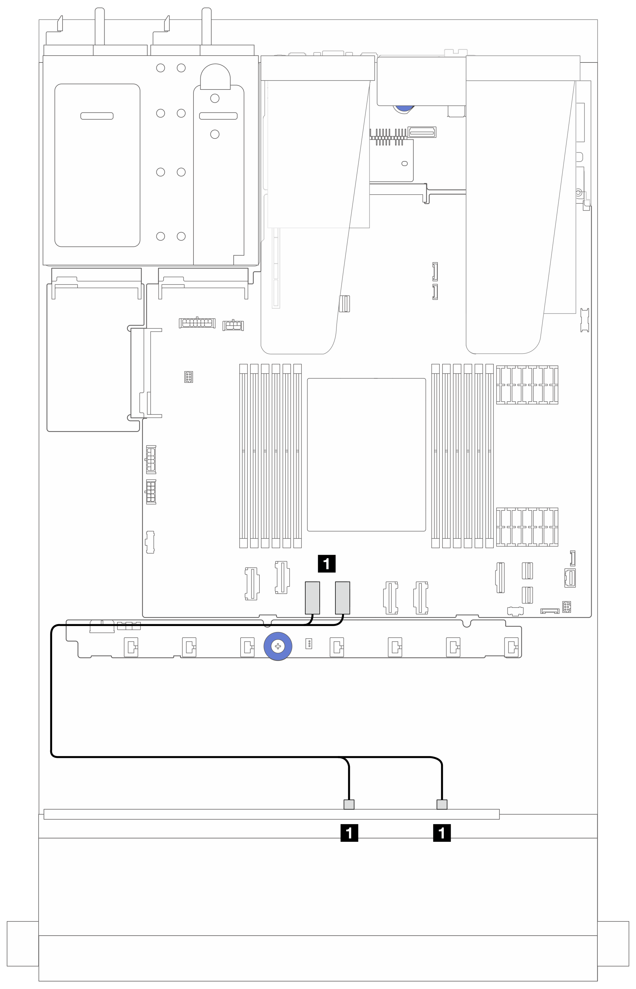
Connections between connectors: 1 ↔ 1, 2 ↔ 2, 3 ↔ 3, ... n ↔ n.Figure 1. Cable routing for NVMe onboard configuration of 6 front SAS/SATA drives and 4 front AnyBay drive bays Table 1. Mapping between one front AnyBay backplane and system board assembly for NVMe onboard configuration| From | To |
|---|
| 1 NVMe 0-1 and 2-3 on the front backplane | 1 PCIe connectors 4 and 3 on the system board assembly |
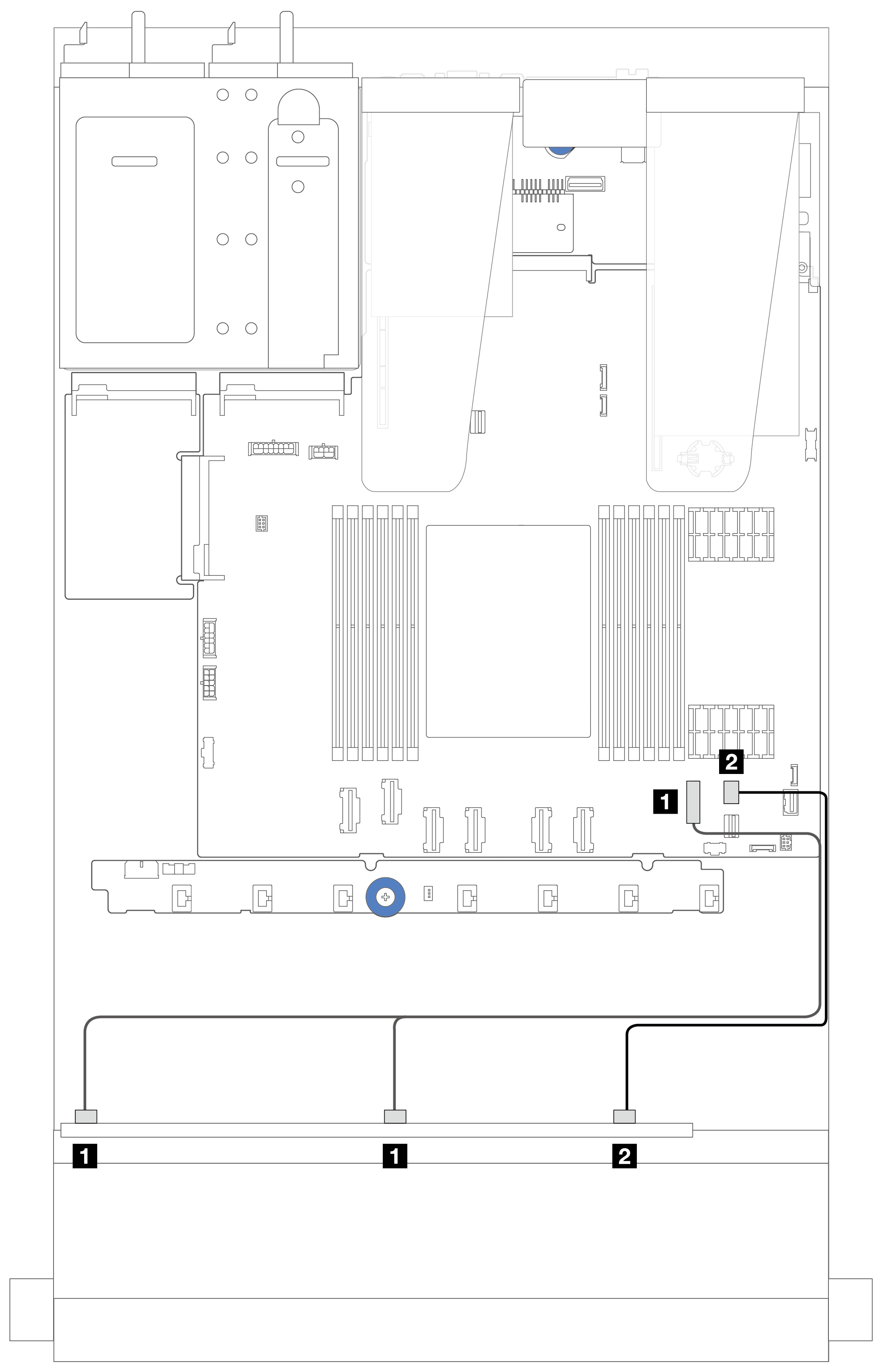
Figure 2. Cable routing for SATA onboard configuration of 6 front SAS/SATA drives and 4 front AnyBay drive bays Table 2. Mapping between one front AnyBay backplane and system board assembly for SAS/SATA onboard configuration| From | To |
|---|
| 1 SAS 0, SAS 1 on the front backplane | 1 PCIe connector 7 on the system board assembly |
| 2 SAS 2 on the front backplane | 2 PCIe connector 8 on the processor board |
The following tables show the mapping relationship between backplane connectors and a 16i SFF HBA/RAID adapter (Gen 3 or Gen 4).
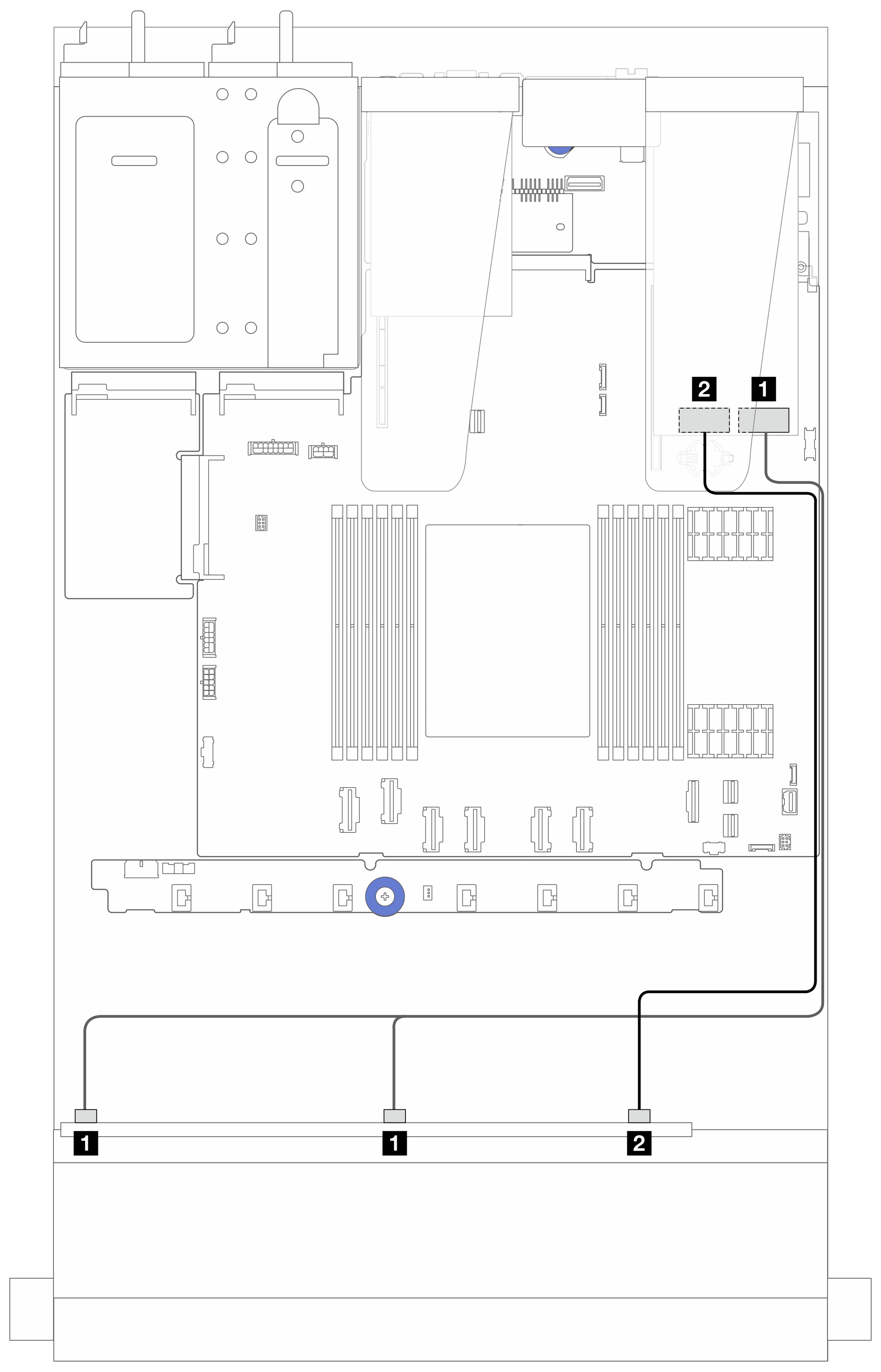
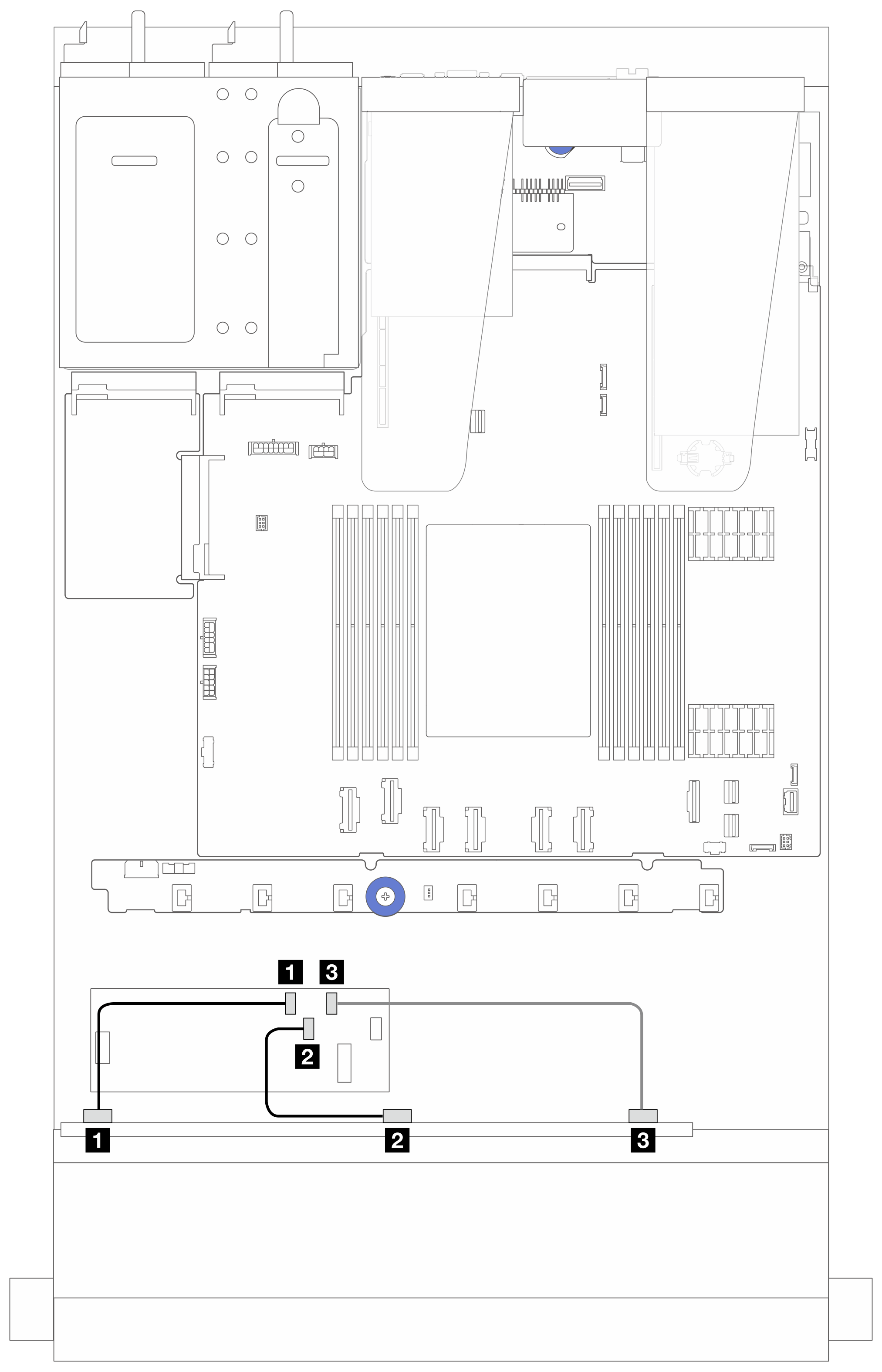
Figure 3. Cable routing for 6 front SAS/SATA drives and 4 front AnyBay drives bays with a 16i SFF RAID adapter (Gen 4) Table 3. Mapping between one front AnyBay backplane and an SFF HBA/RAID adapter (Gen 4)| From | To |
|---|
| 1 SAS 0 and SAS 1 on the front backplane | 1 C0 on the SFF HBA/RAID adapter |
| 3 SAS 2 on the front backplane | 3 C1 on the SFF HBA/RAID adapter |
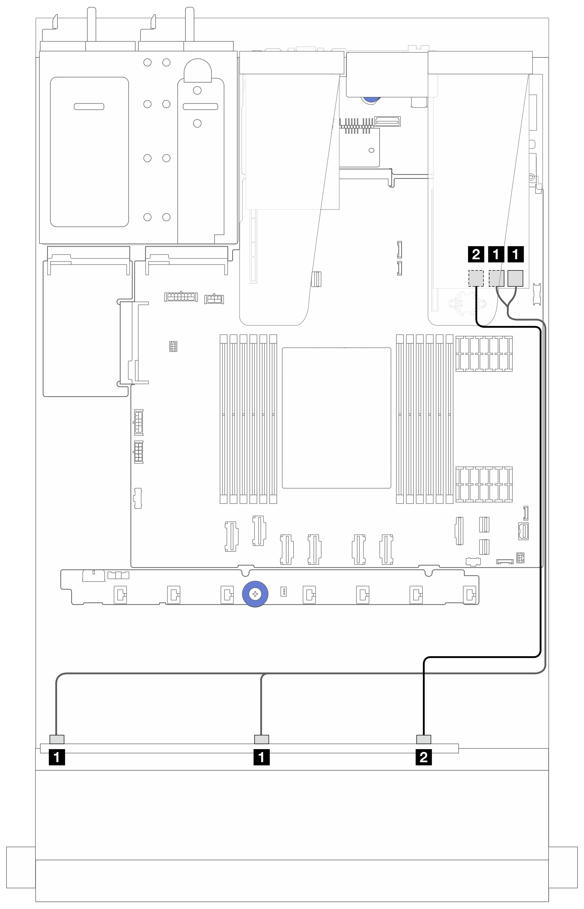
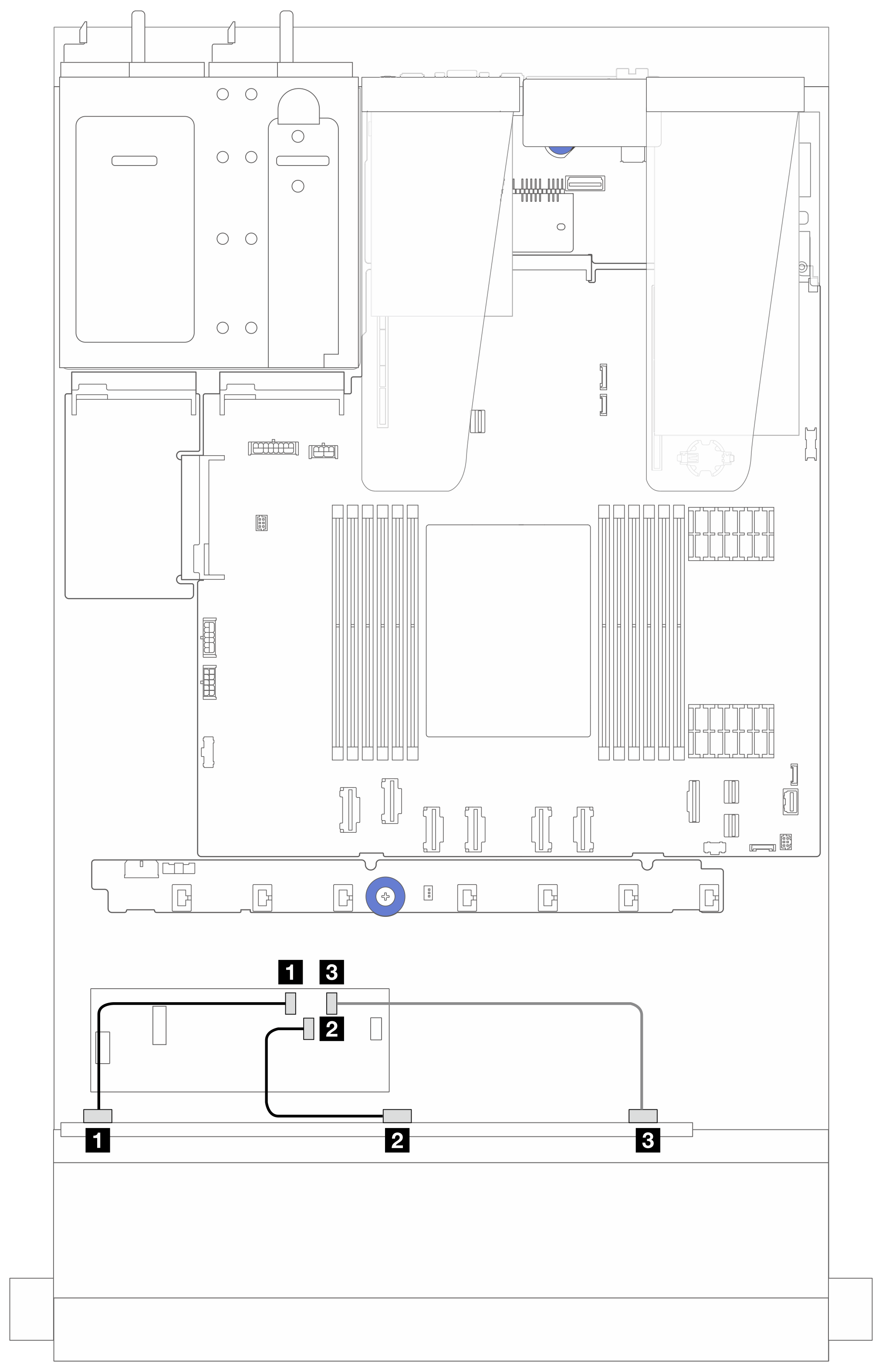
Figure 4. Cable routing for 6 front SAS/SATA drives and 4 front AnyBay drives bays with a 16i SFF RAID adapter (Gen 3) Table 4. Mapping between one front AnyBay backplane and a 16i SFF HBA/RAID adapter (Gen 3)| From | To |
|---|
| 1 SAS 0 and SAS 1 on the front backplane | 1 C0 and C1 on the SFF RAID/HBA adapter |
| 2 SAS 2 on the front backplane | 2 C2 on the SFF RAID/HBA adapter |
Figure 5. Cable routing for 6 front SAS/SATA drives and 4 front AnyBay drives bays and a 16i CFF RAID/HBA adapter (Gen 4) Table 5. Mapping between one front AnyBay and a 16i CFF RAID/HBA adapter (Gen 4)| From | To |
|---|
| 1 SAS 0 on the front backplane | 1 C0 on the CFF RAID/HBA adapter |
| 2 SAS 1 on the front backplane | 2 C1 on the CFF RAID/HBA adapter |
| 3 SAS 2 on the front backplane | 3 C2 on the CFF RAID/HBA adapter |
Figure 6. Cable routing for 6 front SAS/SATA drives and 4 front AnyBay drives bays and a 16i CFF RAID/HBA adapter (Gen 3) Table 6. Mapping between one front AnyBay and a 16i CFF RAID/HBA adapter (Gen 3)| From | To |
|---|
| 1 SAS 0 on the front backplane | 1 C0 on the CFF RAID/HBA adapter |
| 2 SAS 1 on the front backplane | 2 C1 on the CFF RAID/HBA adapter |
| 3 SAS 2 on the front backplane | 3 C2 on the CFF RAID/HBA adapter |
Figure 7. Cable routing for 6 front SAS/SATA drives and 4 front AnyBay drives bays and a 16i CFF RAID adapter (Gen 3 or Gen 4)Gen 3 and Gen 4 16i CFF RAID/HBA adapters are slightly different in their connector locations, but the connection method is similar. The following illustration takes Gen 4 16i CFF RAID/HBA adapters as an example.
Table 7. Mapping between one front AnyBay and a 16i CFF HBA/RAID adapter| From | To |
|---|
| 1 SAS 0 on the front backplane | 1 C0 on the CFF RAID/HBA adapter |
| 2 SAS 1 on the front backplane | 2 C1 on the CFF RAID/HBA adapter |
| 3 SAS 2 on the front backplane | 3 C2 on the CFF RAID/HBA adapter |
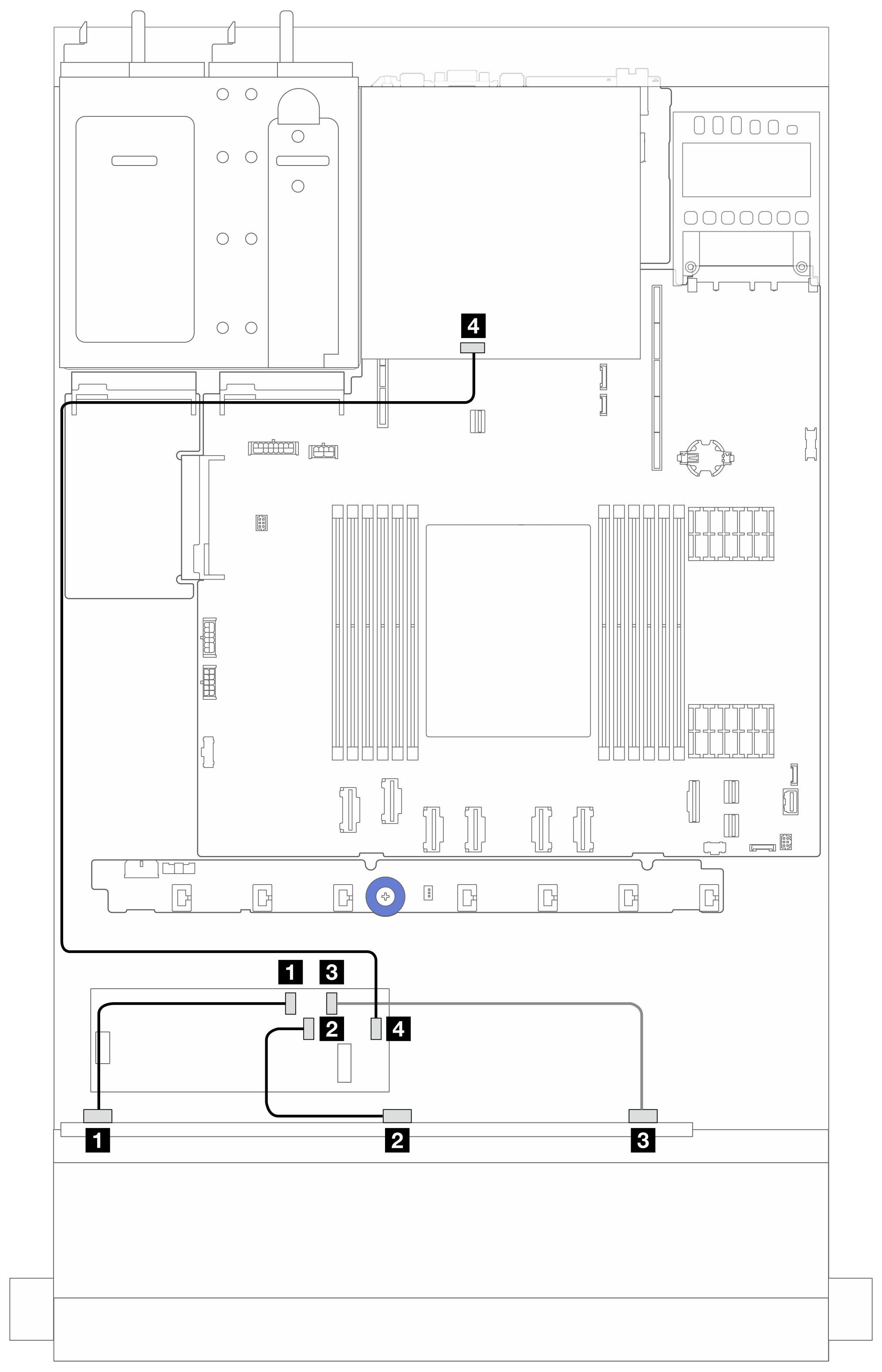
Figure 8. Cable routing for 6 front SAS/SATA drives and 4 front AnyBay drives bays and a 16i CFF RAID adapter (Gen 3/ Gen 4) with 2 x 2.5 rear SAS/SATA drives installedGen 3 and Gen 4 16i CFF RAID/HBA adapters are slightly different in their connector locations, but the connection method is similar. The following illustration takes Gen 4 16i CFF RAID/HBA adapters as an example.
Table 8. Mapping between one front AnyBay backplane and a 16i CFF RAID adapter (Gen 3) with 2 x 2.5 rear SAS/SATA drives installed| From | To |
|---|
| 1 SAS 0 on the front backplane | 1 C0 on the CFF RAID/HBA adapter |
| 2 SAS 1 on the front backplane | 2 C1 on the CFF RAID/HBA adapter |
| 3 SAS 2 on the front backplane | 3 C2 on the CFF RAID/HBA adapter |
| 4 SAS connector on the rear backplane | 4 C3 on the CFF RAID/HBA adapter |