System board assembly replacement (Trained technicians only)
Follow instructions in this section to remove and install the system board assembly.
This task must be operated by trained technicians that are certified by Lenovo Service. Do not attempt to remove or install the part without proper training and qualification.
- If you need to replace a processor board and a firmware and RoT security module together, do the following:
Check the current PSB fuse policy before replacement. See Service process before replacement at Service process for updating PSB fuse state (Lenovo service technicians only).
Ensure that the processor fuse status is expected without unexpected XCC event logs after replacement. See Service process after replacing a processor board and a firmware and RoT security module together at Service process for updating PSB fuse state (Lenovo service technicians only).
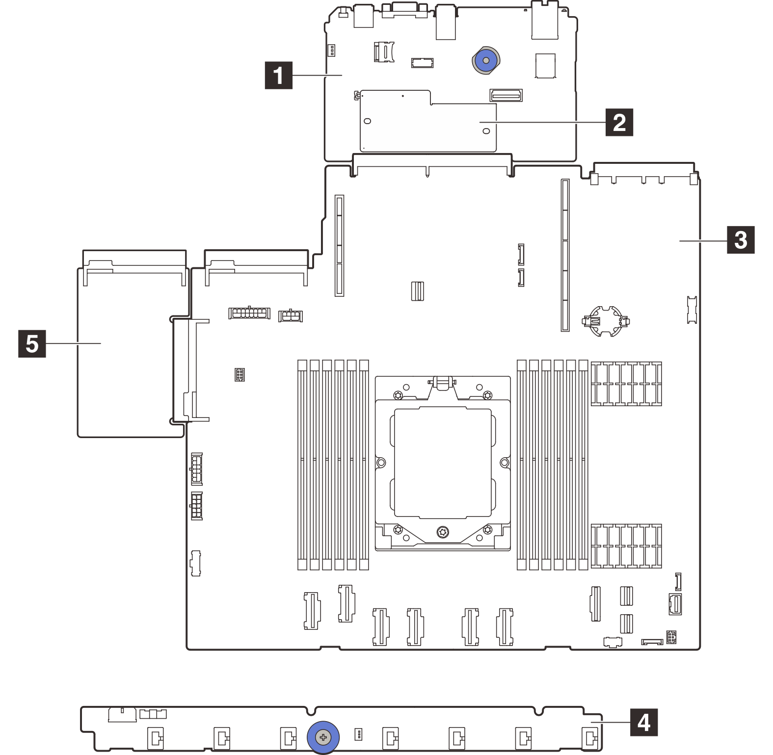
| 1 System I/O board | 2 Firmware and RoT security module |
| 3 Processor board | 4 Fan board |
| 5 PIB board |
For the installation and removal of the fan board and the PIB board, see Fan board replacement and Power inverter board (PIB) replacement.
For the installation and removal of RoT module, I/O board and processor board, see: