Install the processor board
Follow instructions in this section to install the processor board.
About this task
This task must be operated by trained technicians that are certified by Lenovo Service. Do not attempt to remove or install the part without proper training and qualification.
When the server has an L2AM module (Closed loop cooling module) installed, you must apply for a handle (L2AM heat sink bracket) first if you need to install or remove the processor board, I/O board, processor and PIB board. However, while replacing the old L2AM module with a new one, you do not need to apply for a handle (L2AM heat sink bracket) as the new L2AM module contains it.
Read Installation Guidelines and Safety inspection checklist to ensure that you work safely.
Power off the server and peripheral devices and disconnect the power cords and all external cables. See Power off the server.
Prevent exposure to static electricity, which might lead to system halt and loss of data, by keeping static-sensitive components in their static-protective packages until installation, and handling these devices with an electrostatic-discharge wrist strap or other grounding system.
Go to Drivers and Software download website for ThinkSystem SR635 V3 to see the latest firmware and driver updates for your server.
Go to Update the firmware for more information on firmware updating tools.
Procedure
- Install the system board assembly into the server. Figure 1. System board assembly installation
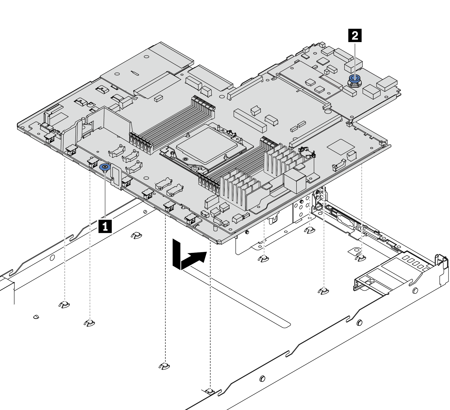
 Hold the lift handle 1 and the release pin 2 at the same time to lower the system board into the chassis.
 Slide the system board to the rear of the server until the system board snaps into position. Ensure that:
The rear connectors on the new system board are inserted into the corresponding holes in the rear panel.
The release pin 2 secures the system board in place.
After you finish
Reconnect all the required cables to the same connectors on the system board assembly. See Internal cable routing.
Ensure that all components have been reassembled correctly and that no tools or loose screws are left inside the server.
Reinstall the top cover. See Install the top cover.
If the sever was installed in a rack, reinstall the server into the rack. See Install the server to rack.
Reconnect the power cords and any cables that you removed.
Power on the server and any peripheral devices. See Power on the server.
If the processor board is replaced, update the vital product data (VPD). See Update the Vital Product Data (VPD).
Machine type number and serial number can be found on the ID label, see Identify the server and access the Lenovo XClarity Controller.
Demo video