10 x 2.5'' NVMe backplane
Use this section to understand the cable routing of 10 NVMe front drives.
To connect power cables for a backplane for standard 2.5'' or 3.5'' drives, refer to Backplane power cable routing.
To connect cables for a rear NVMe/SAS/SATA drive backplane, refer to Rear NVMe/SAS/SATA drive backplane.
To connect signal cables, refer to the following cable routing scenario:
Cable routing for onboard configuration
The following illustrations and tables show the mapping relationship between backplane connectors and system board connectors for onboard configuration.
Figure 1. On-board configuration of 10 x 2.5''NVMe drive backplane
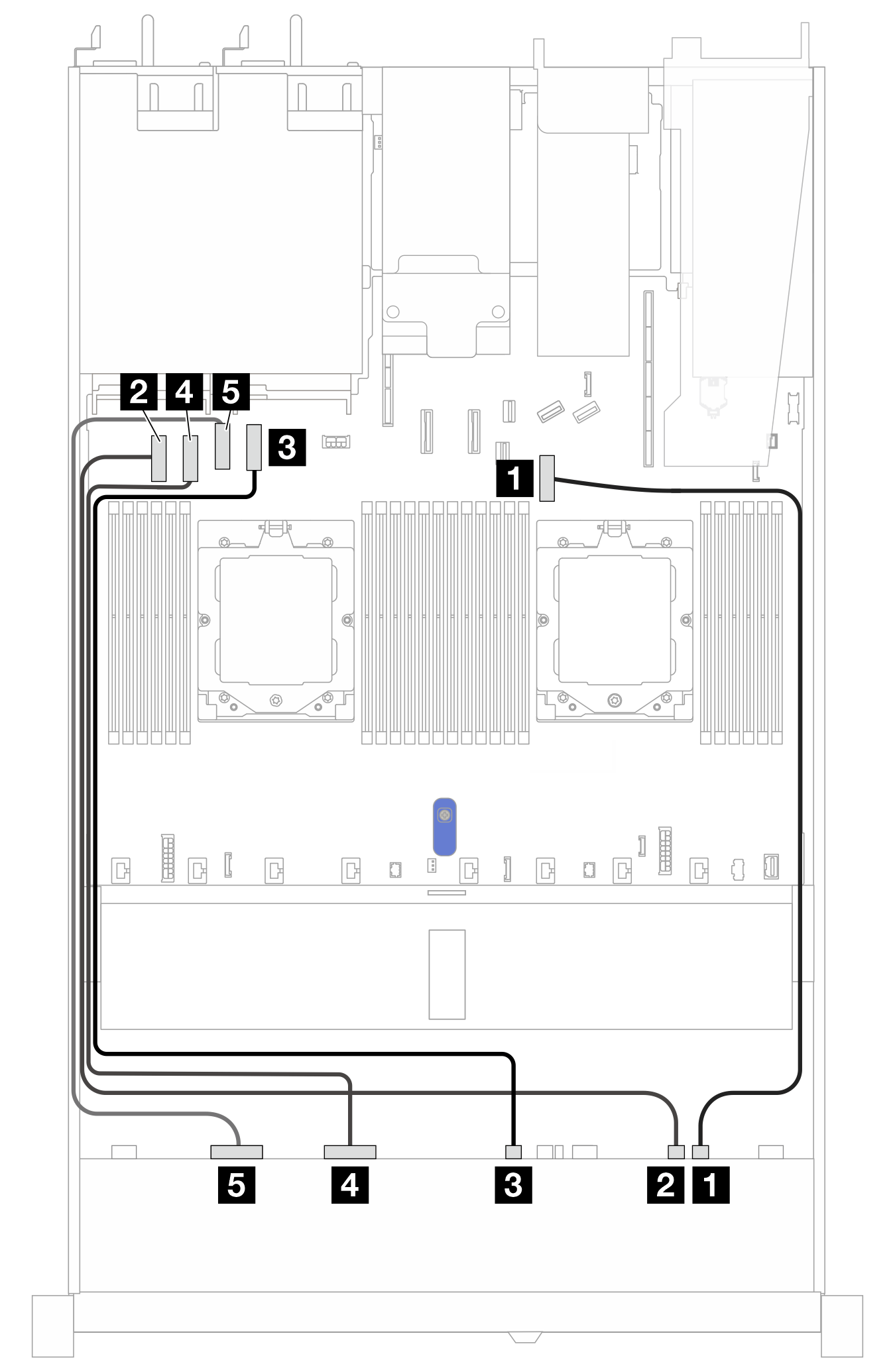
| Backplane | From | To |
|---|---|---|
| Front BP(NVMe) | 1 NVMe 8-9 | 1 PCIe connector 7 |
| 2 NVMe 6-7 | 2 PCIe connector 1 | |
| 3 NVMe 4-5 | 3 PCIe connector 4 | |
| 4 NVMe 2-3 | 4 PCIe connector 2 | |
| 5 NVMe 0-1 | 5 PCIe connector 3 |
Give documentation feedback