4 x 2.5'' AnyBay backplane (Gen 5)
Use this section to understand the cable routing for 4 x 2.5'' AnyBay backplane (Gen 5) with two processors installed.
To connect cables for backplane power, refer to Backplane power cable routing
To connector cables of RAID flash power modules, refer to RAID flash power modules.
To connect cables for front riser assembly, refer to Front riser assembly.
To connect cables for OCP interposer, refer to OCP interposer.
To connect cables for rear 2 x 2.5'' NVMe drive backplane, refer to Rear NVMe/SAS/SATA drive backplane
Cable routing with an SFF HBA/RAID adapter
The following illustrations and tables show the mapping relationship between backplane connectors and an 8i SFF RAID adapter (Gen 3 or Gen 4).
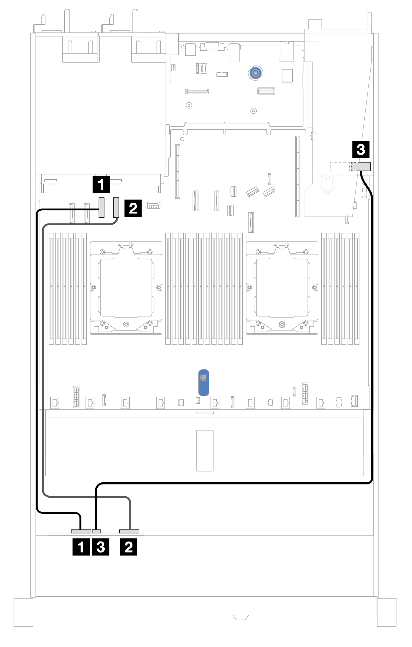
| Backplane | From | To |
|---|---|---|
| Front BP (NVMe) | 1 NVMe 0–1 | 1 PCIe connector 3 |
| 2 NVMe 2–3 | 2 PCIe connector 4 | |
| Front BP (SAS) | 3 SAS | 3 C0 |
Cable routing with an SFF HBA/RAID adapter and a rear 2 x 2.5 SAS/SATA backplane (Gen 3 RAID adapter)
The following illustrations and tables show the mapping relationship between backplane connectors and an 8i SFF RAID adapter (Gen 3).
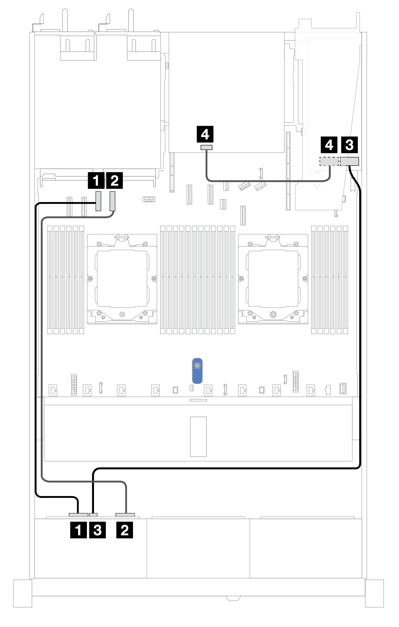
| Backplane | From | To |
|---|---|---|
| Front BP (NVMe) | 1 NVMe 0–1 | 1 PCIe connector 3 |
| 2 NVMe 2–3 | 2 PCIe connector 4 | |
| Front BP (SAS) | 3 SAS | 3 C0 |
| Rear BP (SAS) | 4 SAS | 4 C1 |
Cable routing with an SFF HBA/RAID adapter and a rear 2 x 2.5 SAS/SATA backplane (Gen 4 RAID adapter)
The following illustrations and tables show the mapping relationship between backplane connectors and an 8i SFF RAID adapter (Gen 4).
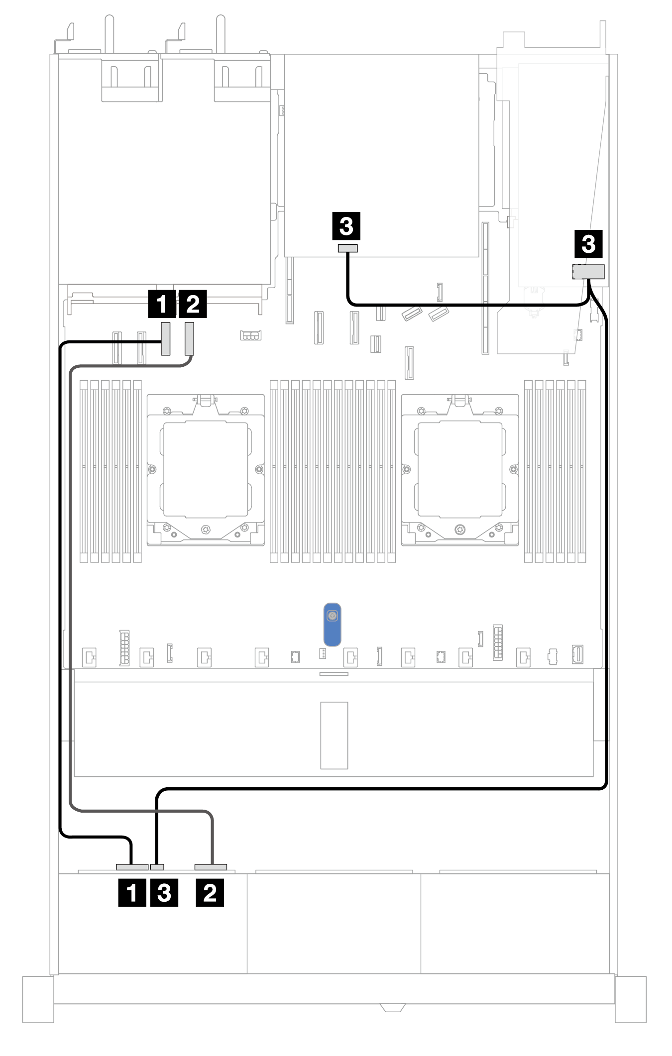
| Backplane | From | To |
|---|---|---|
| Front BP (NVMe) | 1 NVMe 0–1 | 1 PCIe connector 3 |
| 2 NVMe 2–3 | 2 PCIe connector 4 | |
| Front BP/Rear BP (SAS) | 3 SAS | 3 C0 |