4 x 2.5'' NVMe backplane (Gen 4)
Use this section to understand the NVMe backplane (Gen 4) cable routing for server model with four 2.5'' front drives.
To connect power cables for a backplane for standard 2.5'' or 3.5'' drives, refer to Backplane power cable routing.
To connector cables of RAID flash power modules, refer to RAID flash power modules.
To connect cables for intrusion switch, refer to Intrusion switch.
To connect cables for a rear NVMe drive backplane, refer to Rear NVMe/SAS/SATA drive backplane.
To connect signal cables for a backplane for standard 4 x 2.5'' front drives, refer to the following cable routing scenarios depending on your server configuration:
Cable routing for onboard configuration with two processors
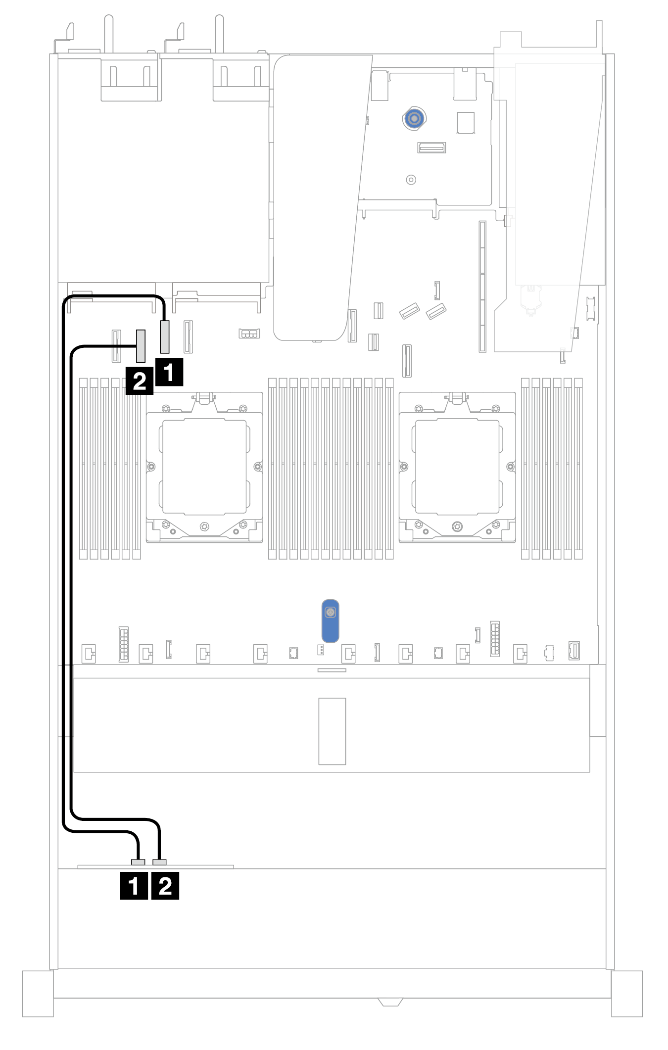
| Backplane | From | To |
|---|---|---|
| Front BP (NVMe) | 1 NVMe 2–3 | 1 PCIe connector 2 |
| 2 NVMe 0–1 | 2 PCIe connector 3 |
Cable routing with front riser assembly and OCP interposer
Ensure the following cables are also connected:
To connect cables for front riser assembly, refer to Front riser assembly.
To connect cables for OCP interposer, refer to OCP interposer.
Figure 1. Cable routing for 4 x 2.5'' front NVMe drive bays for front riser assembly and OCP interposer configuration
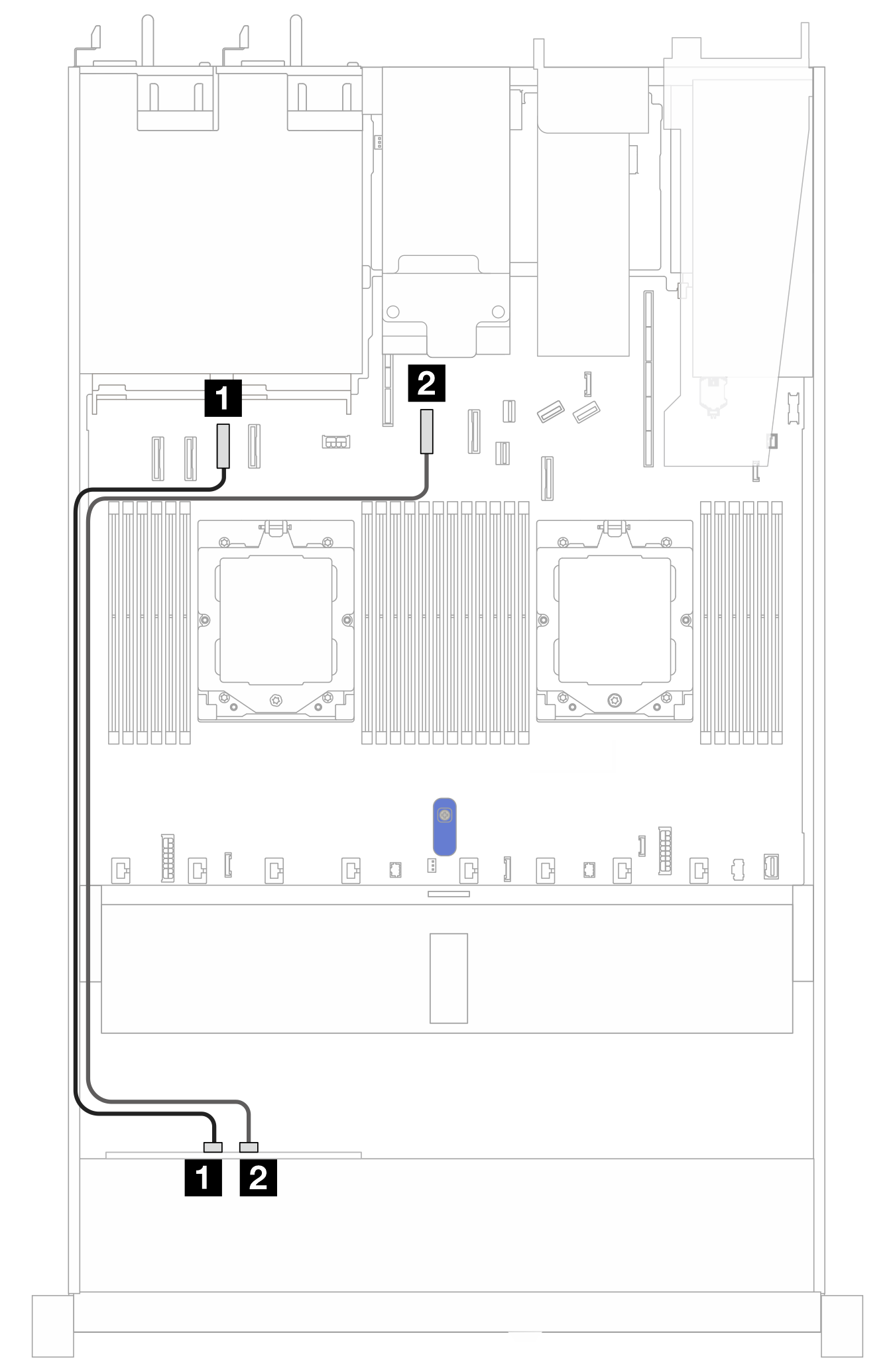
| Backplanes | From | To |
|---|---|---|
| Front BP (NVMe) | 1 NVMe 0–1 | 1 PCIe connector 3 |
| 2 NVMe 2–3 | 2 PCIe connector 5 |
Give documentation feedback