Install a power supply unit
Use this information to install a power supply.
About this task
The server is shipped with only one power supply by default. In this case, the power supply is non-hot-swappable. To support redundancy mode or hot-swap, install an additional hot-swap power supply.
Use Lenovo Capacity Planner to calculate the required power capacity for what is configured for your server. More information about Lenovo Capacity Planner is available at:
Ensure that the devices that you are installing are supported. For a list of supported optional devices for the server, go to:
Attach the power information label that comes with this option onto the top cover near the power supply.
Figure 1. Example power supply label on the top cover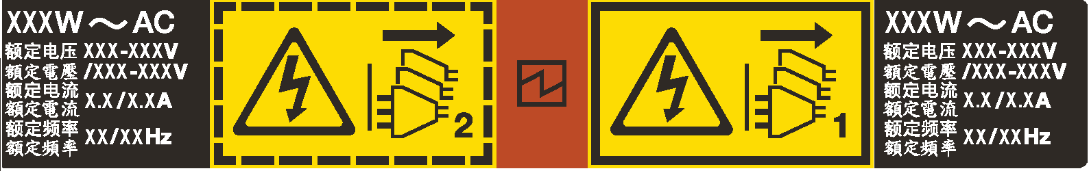
Safety precautions for AC power supplies
The following tips describe the information that you must consider when you install an AC power supply.
S035 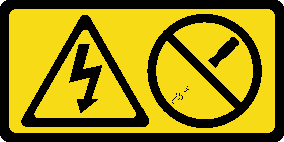 CAUTION Never remove the cover on a power supply or any part that has this label attached. Hazardous voltage, current, and energy levels are present inside any component that has this label attached. There are no serviceable parts inside these components. If you suspect a problem with one of these parts, contact a service technician. |
S002 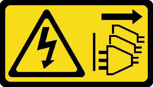 CAUTION The power-control button on the device and the power switch on the power supply do not turn off the electrical current supplied to the device. The device also might have more than one power cord. To remove all electrical current from the device, ensure that all power cords are disconnected from the power source. |
To avoid a shock hazard:
- Connect all power cords to a properly wired and grounded electrical outlet/source.
- Connect any equipment that will be attached to this product to properly wired outlets/sources.
- When possible, use one hand only to connect or disconnect signal cables.
- Never turn on any equipment when there is evidence of fire, water, or structural damage.
- The device might have more than one power cord, to remove all electrical current from the device, ensure that all power cords are disconnected from the power source.
Safety precautions for DC power supplies
The following tips describe the information that you must consider when you install a DC power supply.
CAUTION  240 V DC input (input range: 180-300 V) is supported in Chinese Mainland ONLY. Perform the following steps to safely remove the power cord of one 240 V DC power supply unit. Otherwise, there can be data loss and other damages to the equipment. Damages and losses resulting from inappropriate operations will not be covered by the manufacturer’s warranty.
|
S035 CAUTION Never remove the cover on a power supply or any part that has this label attached. Hazardous voltage, current, and energy levels are present inside any component that has this label attached. There are no serviceable parts inside these components. If you suspect a problem with one of these parts, contact a service technician. |
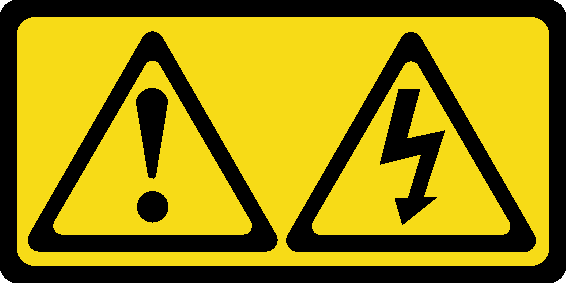
S019 CAUTION The power-control button on the device does not turn off the electrical current supplied to the device. The device also might have more than one connection to dc power. To remove all electrical current from the device, ensure that all connections to dc power are disconnected at the dc power input terminals. |
To avoid a shock hazard:
- To connect or disconnect -48V dc power cables when you need to remove/install redundancy power supply unit(s).
| To Connect: | To Disconnect: |
|---|---|
|
|
Procedure
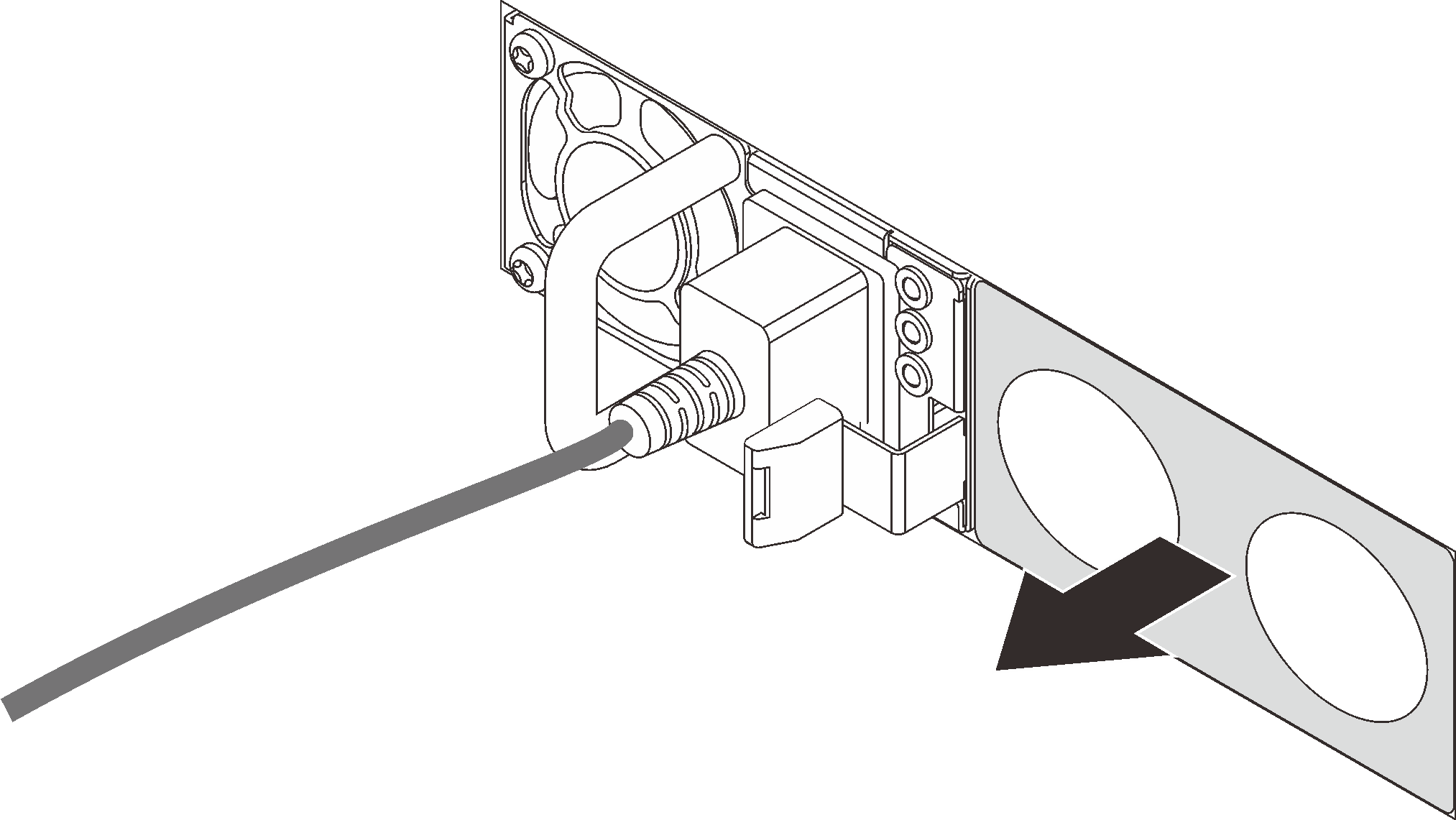
- If there is a power-supply filler installed, remove it.Figure 2. Hot-swap power supply filler removal
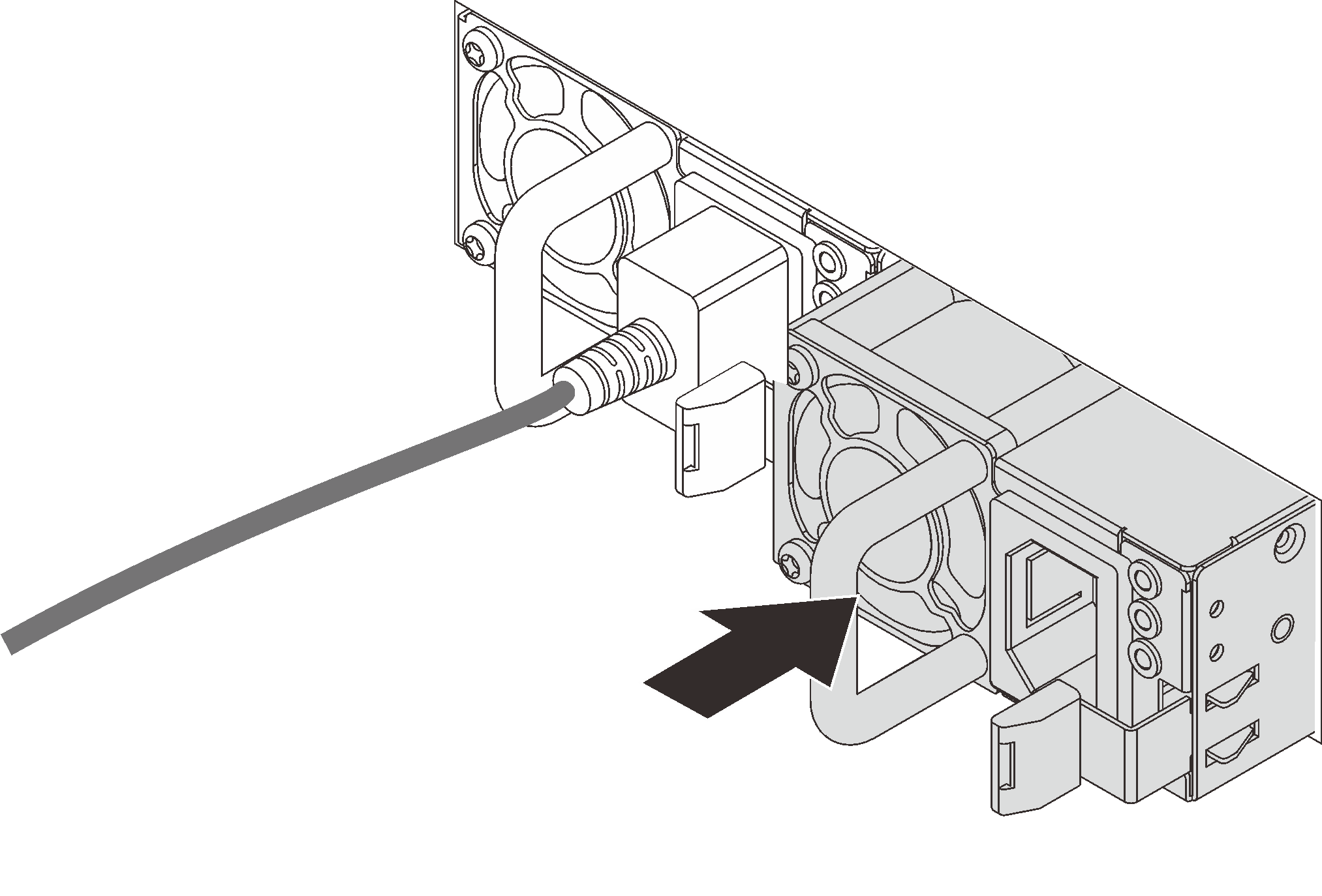
- Slide the new hot-swap power supply into the bay until it snaps into position.Figure 3. Hot-swap power supply installation
- Connect the power supply unit to a properly grounded electrical outlet.
For AC power supply units:
Connect one end of the power cord to the power connector on the power supply unit.
Connect the other end of the power cord to a properly grounded electrical outlet.
For –48V DC power supply units:
Use a slotted screwdriver to loosen the 3 captive screws on the power supply terminal block.
- Check the type label on the power supply block and each power cord.
Type PSU terminal block Power cord Input 
-Vin Ground 
GND Input 
RTN Face the groove side of each power cord pin upwards, plug the pins into corresponding holes on the power block, use the table above for guidance, and ensure that the pins find correct slots.
Tighten the captive screws on the power block, and ensure that the screws and cord pins are secured in place and no bare metal parts show.
Connect the other end of the cables to a properly grounded electrical outlet, and ensure that the cable ends find correct outlets.
Demo video