Install a processor-heat-sink module
This task has instructions for installing processors and heat sinks. Heat sink replacement requires a Torx #T20 screwdriver.
About this task
Read Installation Guidelines to ensure that you work safely.
Power off the server and disconnect all power cords for this task.
Prevent exposure to static electricity, which might lead to system halt and loss of data, by keeping static-sensitive components in their static-protective packages until installation, and handling these devices with an electrostatic-discharge wrist strap or other grounding system.
The heat sink is necessary to maintain proper thermal conditions for the processor. Do not power on the server with the heat sink removed.
Do not touch the processor socket or processor contacts. Processor-socket contacts are very fragile and easily damaged. Contaminants on the processor contacts, such as oil from your skin, can cause connection failures.
Do not allow the thermal grease on the processor or heat sink to come in contact with anything. Contact with any surface can compromise the thermal grease, rendering it ineffective. Thermal grease can damage components, such as electrical connectors in the processor socket. Do not remove the grease cover from a heat sink until you are instructed to do so.
See Lenovo ServerProven website for a list of processors supported for your server. All processors on the system board must have the same speed, number of cores, and frequency.
Before you install a new processor, update your system firmware to the latest level. See Update the firmware.
Optional devices available for your system might have specific processor requirements. See Technical rules.
Procedure
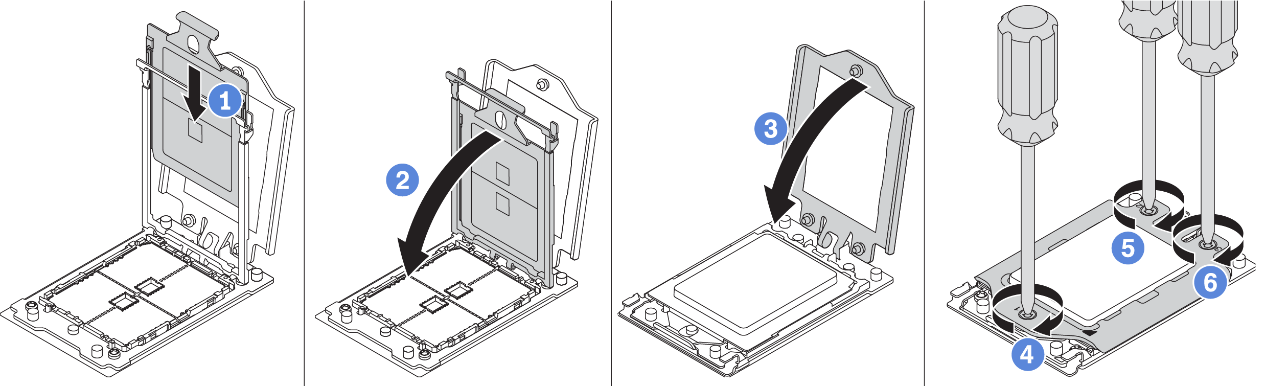
- Install the processors.Figure 1. Processor installation
- Install the standard or performance heat sink.NoteFor a new heat sink, the thermal grease is pre-applied to the heat sink. Remove the protective cover and install the heat sink.NoteUse an ESD safe screwdriver and set the maximum torque value to 14.0 ± 0.5 inch-pounds.Figure 2. Installing a standard heat sink
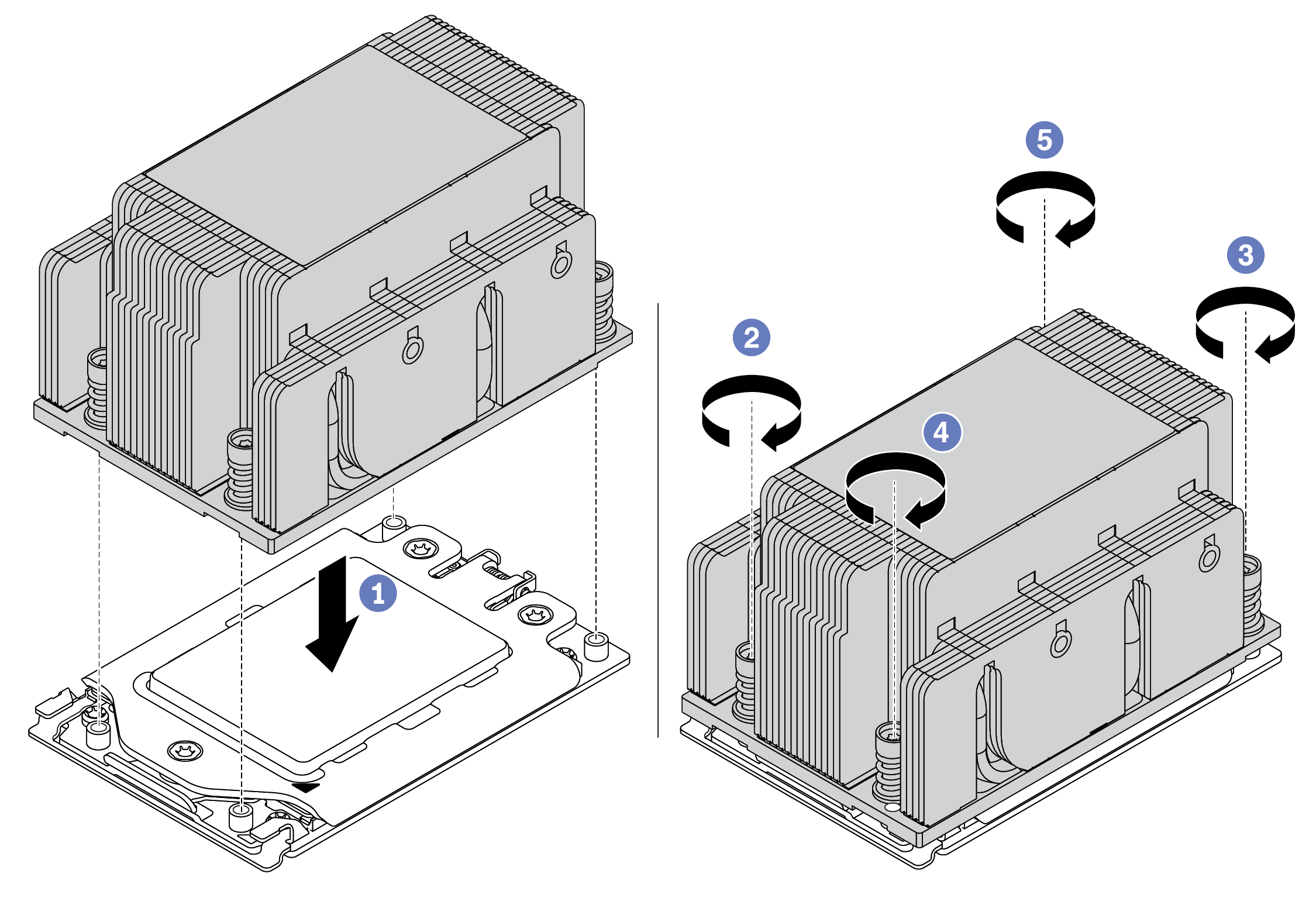 Figure 3. Installing a performance heat sink
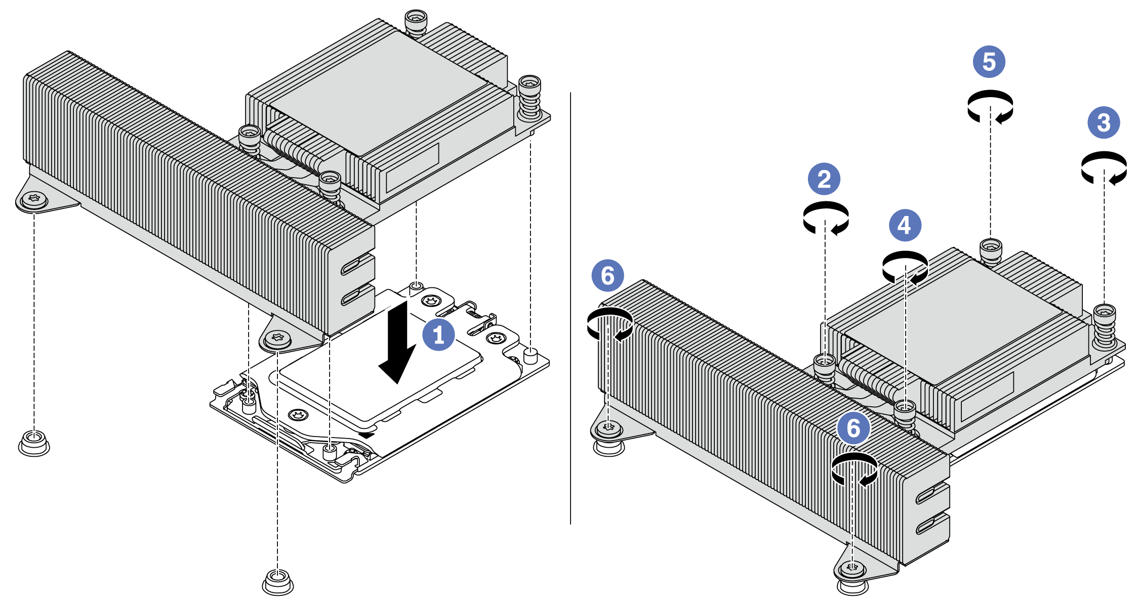
After you finish
Install any options that you have purchased.
Demo video