Install a hot-swap power supply unit
Use this information to install a hot-swap power supply.
About this task
The server is shipped with only one power supply by default. In this case, the power supply is non-hot-swap and before removing it, you must turn off the server first. To support redundancy mode or hot-swap, install an additional hot-swap power supply.
The server does not support setting the redundancy mode manually. The BMC of the server can automatically set it based on the installed power supply unit quantity.
When only 1 power supply unit is installed, the redundancy mode is set to
Non-redundant mode
.When 2 power supply units are installed, the redundancy mode is set to
Redundant (N+N)
. If one of the power supply units fails or has been removed, the BMC will report an event and set the redundancy mode toNon-redundant mode
automatically.
- If you are replacing the existing power supply with a new power supply:
Use Lenovo Capacity Planner to calculate the required power capacity for what is configured for your server. For details, see:
- Ensure that the devices that you are installing are supported. For details, see: Lenovo ServerProven website
Attach the label coming with this option onto the existing label near the power supply.
Figure 1. Example label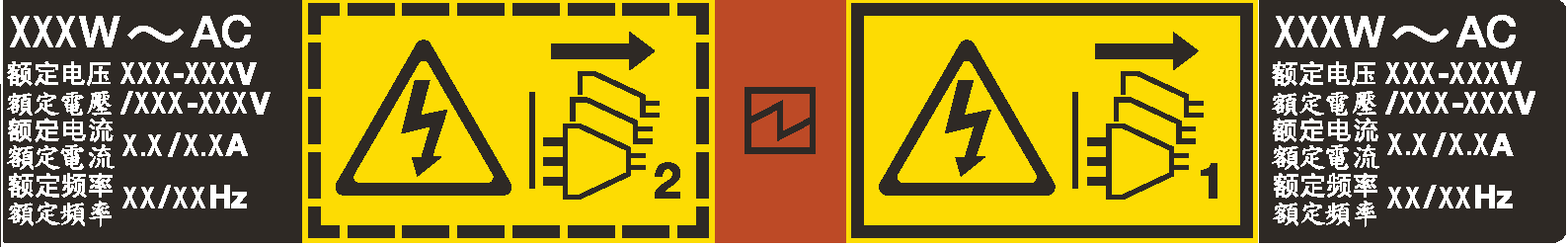
Read Installation Guidelines to ensure that you work safely.
Prevent exposure to static electricity, which might lead to system halt and loss of data, by keeping static-sensitive components in their static-protective packages until installation, and handling these devices with an electrostatic-discharge wrist strap or other grounding system.
Procedure
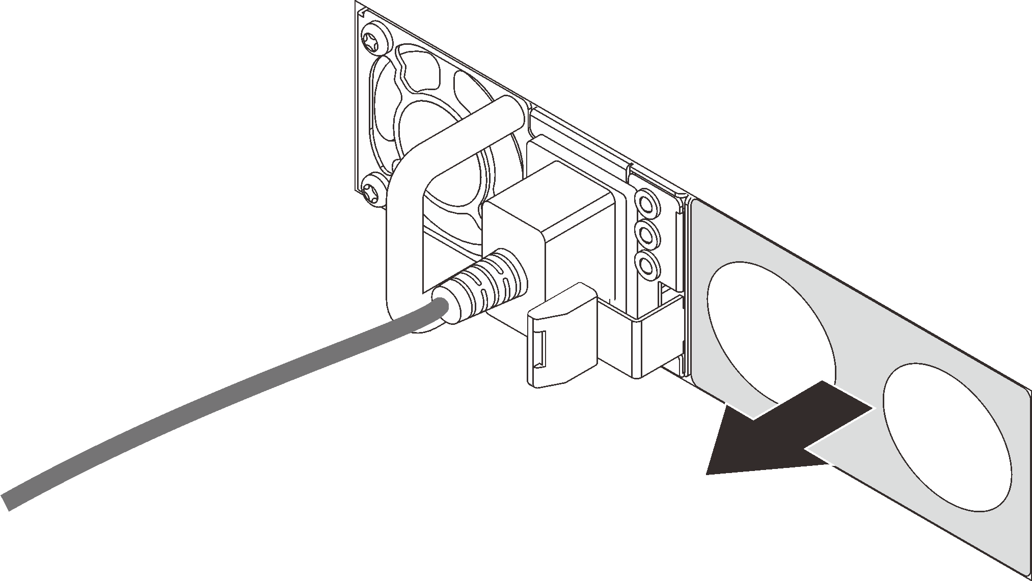
- If there is a power-supply filler installed, remove it.Figure 2. Hot-swap power supply filler removal
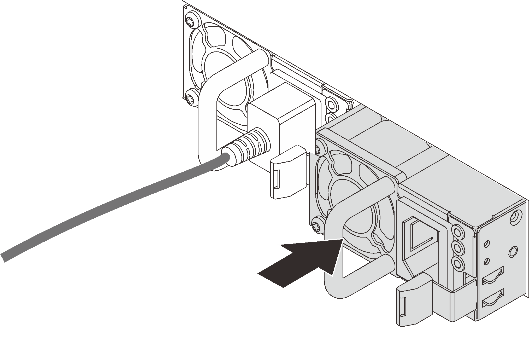
- Slide the new hot-swap power supply into the bay until it snaps into position.Figure 3. Hot-swap power supply installation
- Connect the power cord(s).
For 240 V DC power supply units:
Turn off the server.
Connect one end of the power cord to the power connector on the power supply unit.
Connect the other end of the power cord to a properly grounded electrical outlet.
For AC power supply units:
Connect one end of the power cord to the power connector on the power supply unit.
Connect the other end of the power cord to a properly grounded electrical outlet.
For –48V DC power supply units:
Use a slotted screwdriver to loosen the 3 captive screws on the power supply terminal block.
- Check the type label on the power supply block and each power cord.
Type PSU terminal block Power cord Input 
-Vin Ground 
GND Output 
RTN Face the groove side of each power cord pin upwards, and then plug the pins into corresponding holes on the power block. Use the table above for guidance to ensure that the pins find correct slots.
Tighten the captive screws on the power block. Ensure that the screws and cord pins are secured in place and no bare metal parts are shown.
Connect the other end of the cables to a properly grounded electrical outlet. Ensure that the cable ends find correct outlets.
Demo video