Remove the system board
Follow instructions in this section to remove the system board.
About this task
Removing and installing this component requires trained technicians. Do not attempt to remove or install it without proper training.
- When replacing the system board, always update the server with the latest firmware or restore the pre-existing firmware. Make sure that you have the latest firmware or a copy of the pre-existing firmware before you proceed.
When removing the memory modules, label the slot number on each memory module, remove all the memory modules from the system board, and set them aside on a static-protective surface for reinstallation.
When disconnecting cables, make a list of each cable and record the connectors the cable is connected to, and use the record as a cabling checklist after installing the new system board.
Read Installation Guidelines and Safety inspection checklist to ensure that you work safely.
Power off the server and peripheral devices and disconnect the power cords and all external cables. See Power off the server.
If the server is installed in a rack, slide the server out on its rack slide rails to gain access to the top cover, or remove the server from the rack. See Remove the server from rack.
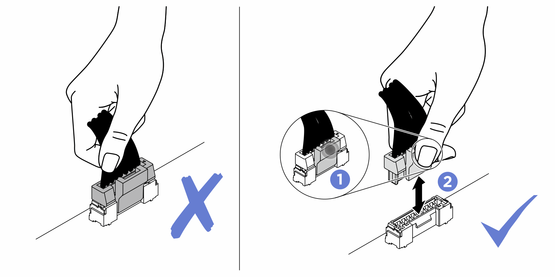
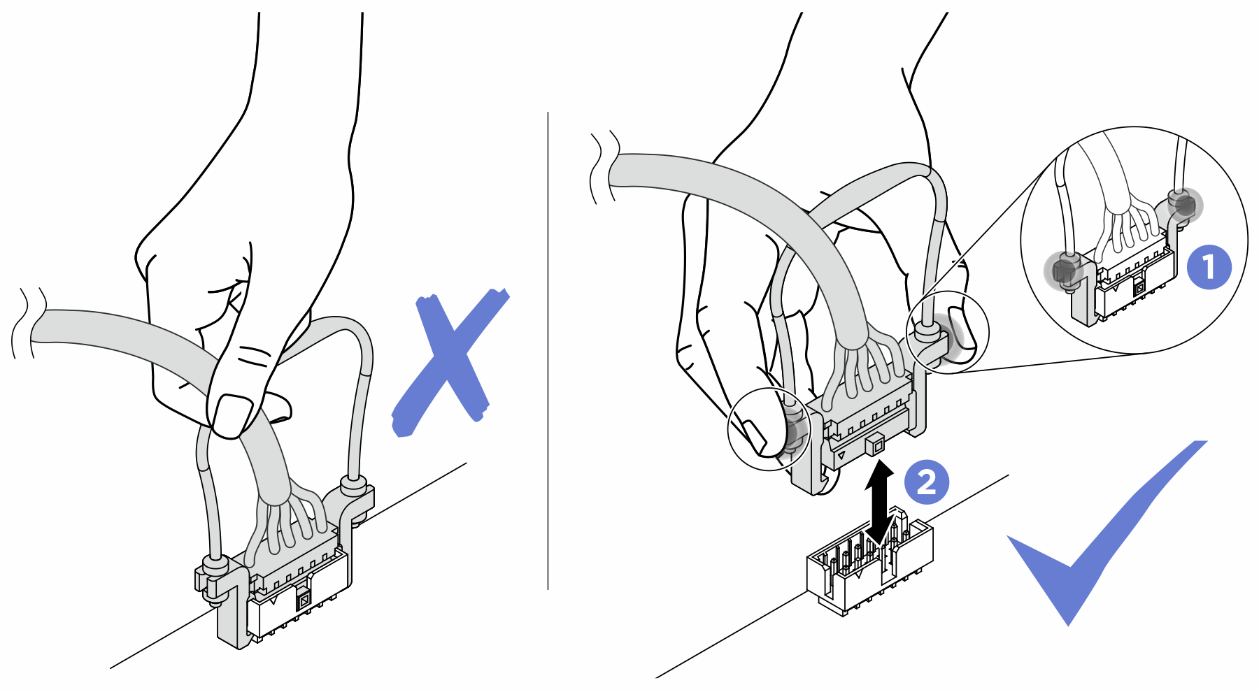
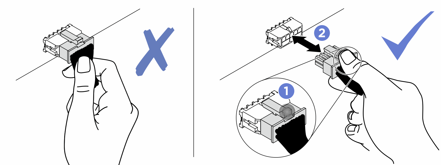
Connect cable connectors vertically or horizontally in alignment with the orientations of the corresponding cable sockets, avoiding any tilt.
- To disconnect cables from the system board, do as follows:
Press and hold all latches, release tabs, or locks on cable connectors to release the cable connectors.
- Remove the cable connectors vertically or horizontally in alignment with the orientations of the corresponding cable sockets, avoiding any tilt.NoteThe cable connectors might look different from those in the illustration, but the removal procedure is the same.
Procedure
- Prepare your server.
- Record all system configuration information, such as Lenovo XClarity Controller IP addresses, vital product data, and the machine type, model number, serial number, Universally Unique Identifier, and asset tag of the server.
- Save the system configuration to an external device with Lenovo XClarity Essentials.
- Save the system event log to external media.
- Remove the following components in the sequence below.
- Disconnect all the cables from the system board. As you disconnect the cable, make a list of each cable and record the connectors the cable is connected to, and use the record as a cabling checklist after installing the new system board.
- Disengage the system board.
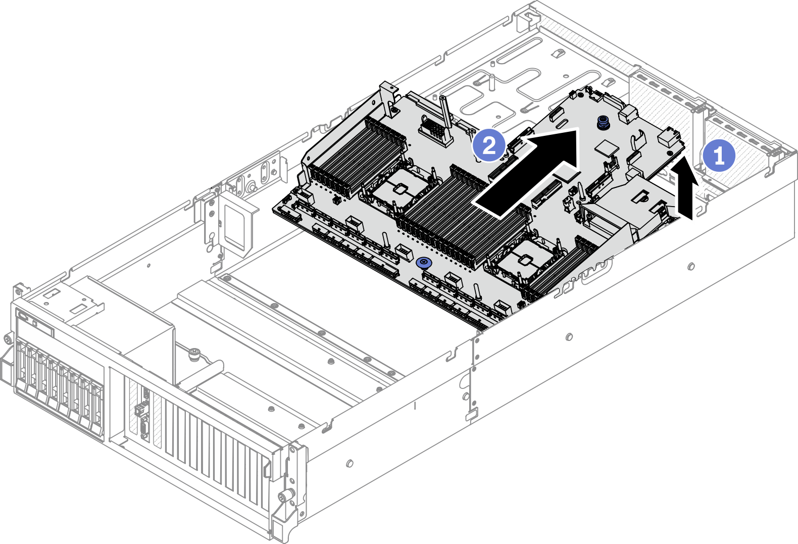
 Pull up the rear lifting handle to release the system board.
 Grasp both lifting handles, and slide the system board toward the front of the chassis. Make sure that the guide pin is at the rear end of the guide slot.NoteThis handle only serves the purpose of removing system board. Do not attempt to lift the whole server with it.Figure 1. Disengaging the system board
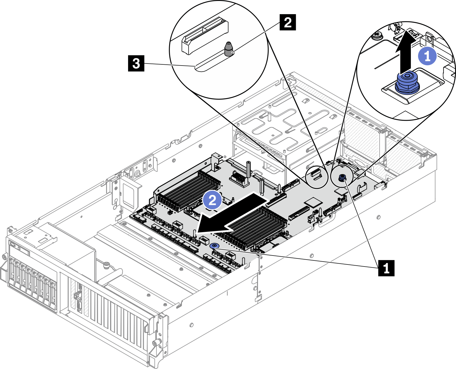
1 Lifting handles 2 Guide pin 3 Guide slot
- Remove the system board.
- Tilt the system board so that its rear end is up.
- Hold both lifting handles, and lift the system board out of the chassis.Figure 2. Removing the system board
After you finish
If you are instructed to return the component or optional device, follow all packaging instructions, and use any packaging materials for shipping that are supplied to you.
ImportantBefore you return the system board, make sure that you install the CPU socket covers from the new system board. To replace a CPU socket cover:Take a socket cover from the CPU socket assembly on the new system board and orient it correctly above the CPU socket assembly on the removed system board.
Gently press down the socket cover legs to the CPU socket assembly, pressing on the edges to avoid damage to the socket pins. You might hear a click on the socket cover is securely attached.
Make sure that the socket cover is securely attached to the CPU socket assembly.
If you plan to recycle the component, see Disassemble the system board for recycle.
Demo video