Install the system board
Follow instructions in this section to install the system board.
About this task
Removing and installing this component requires trained technicians. Do not attempt to remove or install it without proper training.
Read Installation Guidelines and Safety inspection checklist to ensure that you work safely.
Touch the static-protective package that contains the component to any unpainted metal surface on the server; then, remove it from the package and place it on a static-protective surface.
Procedure
- Placing the system board inside the chassis.
 Grasp the lifting handles on system board, and tilt the system board so that its rear end is up.
 Align the guide slot on system board with the guide pin on chassis; then, lower the system board into the chassis.
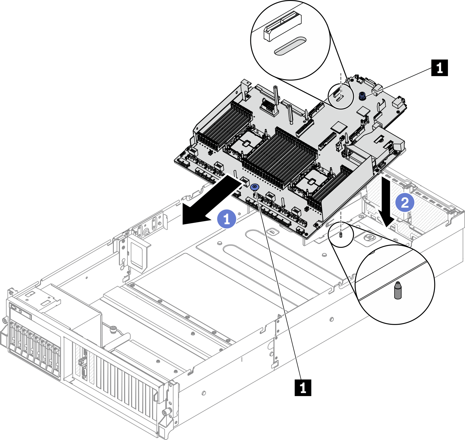
1 Lifting handle - Grasp the lifting handles, and slide the system board toward the rear of the chassis. Make sure that:
The guide pin is at the front end of the guide slot.
The rear connectors on the new system board are inserted into the corresponding holes in the rear panel.
Figure 1. Installing the system board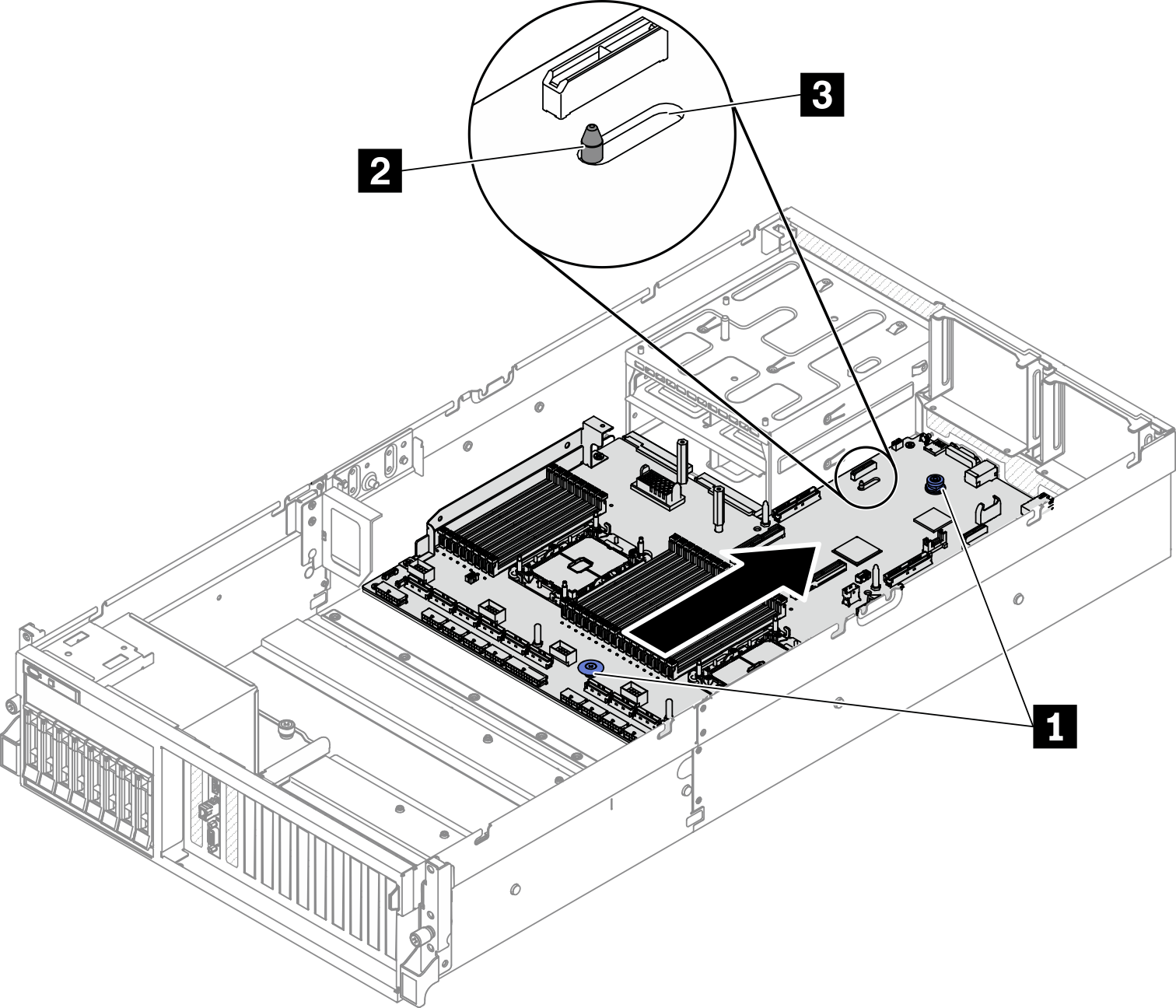
1 Lifting handles 2 Guide pin 3 Guide slot
After you finish
Install the following components in the sequence below.
Install the power distribution board. See Install the power distribution board.
(SXM GPU Model only) Install the SXM GPU power distribution board. See Install the SXM GPU power distribution board.
Install the power supply units. See Install a power supply unit.
If applicable, install the OCP Ethernet adapter. See Install the OCP Ethernet adapter.
If applicable, install the PCIe riser. See Install a PCIe riser.
Install the intrusion switch. See Install the intrusion switch.
Install each memory module to the same slot on the new system board as on the defective system board until all the memory modules are installed. See Install a memory module.
Install the PHMs. See Install a processor and heat sink.
Install the air baffle. See Install the air baffle.
Reconnect all the required cables to the same connectors on the system board as the defective system board.
Install the fan cage and the fans. See Install the fan cage and Install a fan.
Ensure that all components have been reassembled correctly and that no tools or loose screws are left inside the server.
Reinstall the top cover. See Install the top cover.
If the sever was installed in a rack, reinstall the server into the rack. See Install the server to rack.
Reconnect the power cords and any cables that you removed.
Power on the server and any peripheral devices. See Power on the server.
Update the machine type and serial number with new vital product data (VPD). Use the Lenovo XClarity Provisioning Manager to update the machine type and serial number. See Update the machine type and serial number.
Enable TPM. See Enable TPM.
Optionally, enable UEFI Secure Boot. See Enable UEFI Secure Boot.
Demo video