Remove the interposer card
Follow instructions in this section to remove the interposer card. The procedure must be executed by a trained technician.
About this task
Attention
- Read Installation Guidelines and Safety inspection checklist to ensure that you work safely.
- Power off the server and peripheral devices and disconnect the power cords and all external cables. See Power off the server.
- If the server is installed in a rack, slide the server out on its rack slide rails to gain access to the top cover, or remove the server from the rack. See Remove the server from rack.
Procedure
- Make preparation for this task.
- Unfasten the two cable ties on the front drive tray to release the cables.Figure 1. Unfastening the cable ties
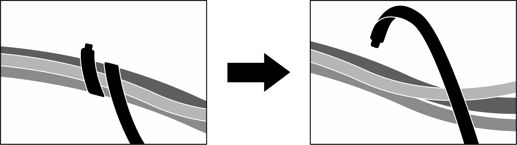
- Unfasten the two cable ties on the front drive tray to release the cables.
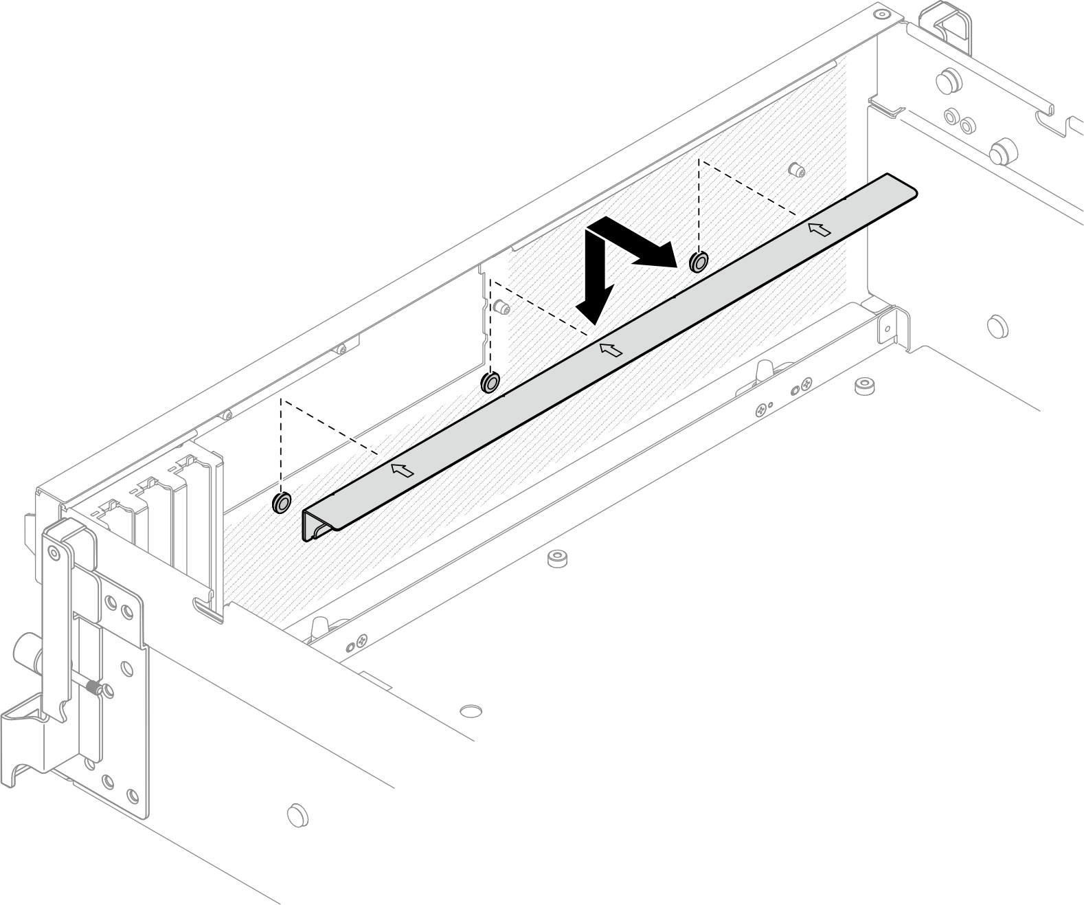
- Lift the front drive tray support bracket, and remove it out of the chassis.Figure 2. Front drive tray support bracket removal
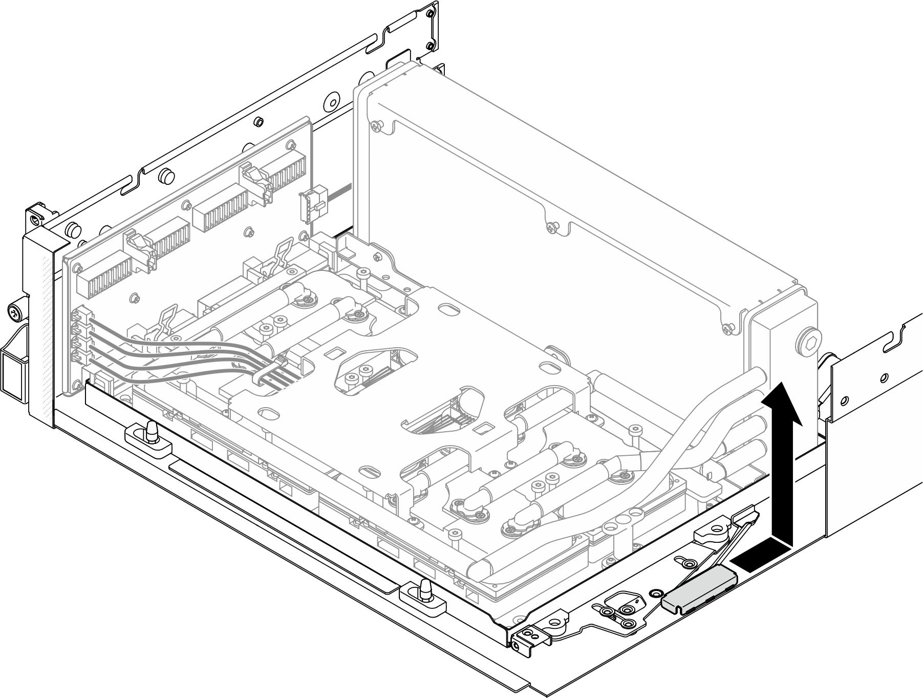
- Slide the SXM5 GPU board assembly retention bracket backward, and lift it out of the chassis.Figure 3. SXM5 GPU board assembly retention bracket removal
- Pull out the SXM5 GPU board assembly latch outward until it stops; then, rotate down the SXM5 GPU board assembly handle so that the two retention clips are facing up.Figure 4. GPU-L2A assembly adjustment
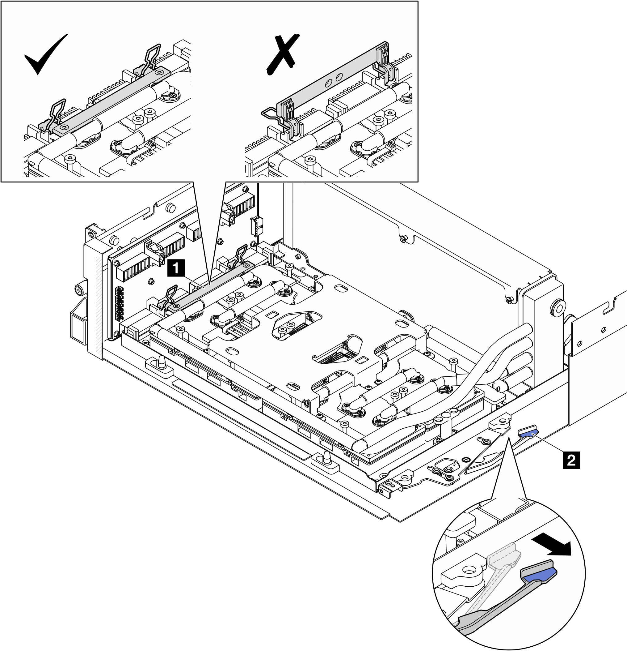
1 SXM5 GPU board assembly handle 2 SXM5 GPU board assembly latch - Slightly slide up the interposer card to disengage it from the chassis.Figure 5. Interposer card disengagement
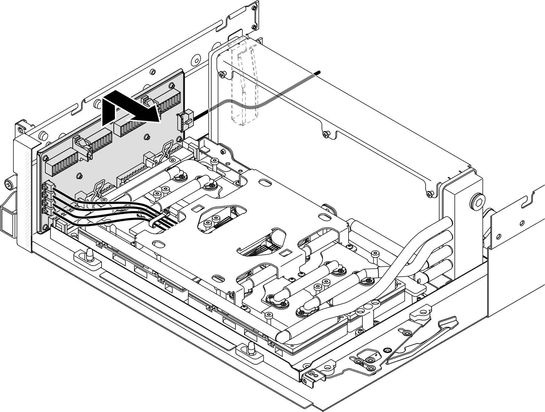
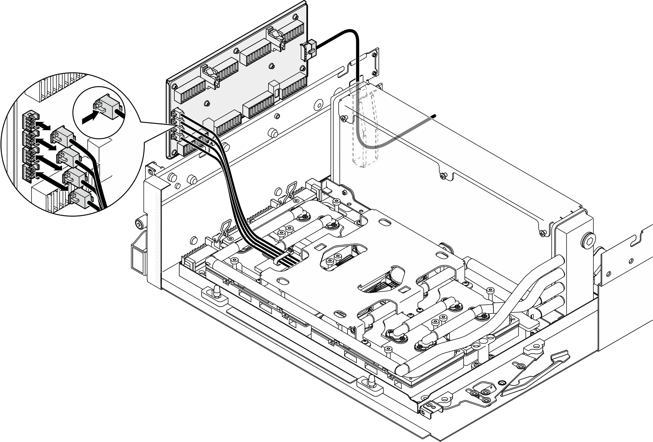
- Slightly press and hold the cable latch; then, disconnect the four cold plate assembly pump cables from the interposer card.Figure 6. Cold plate assembly pump cable disconnection
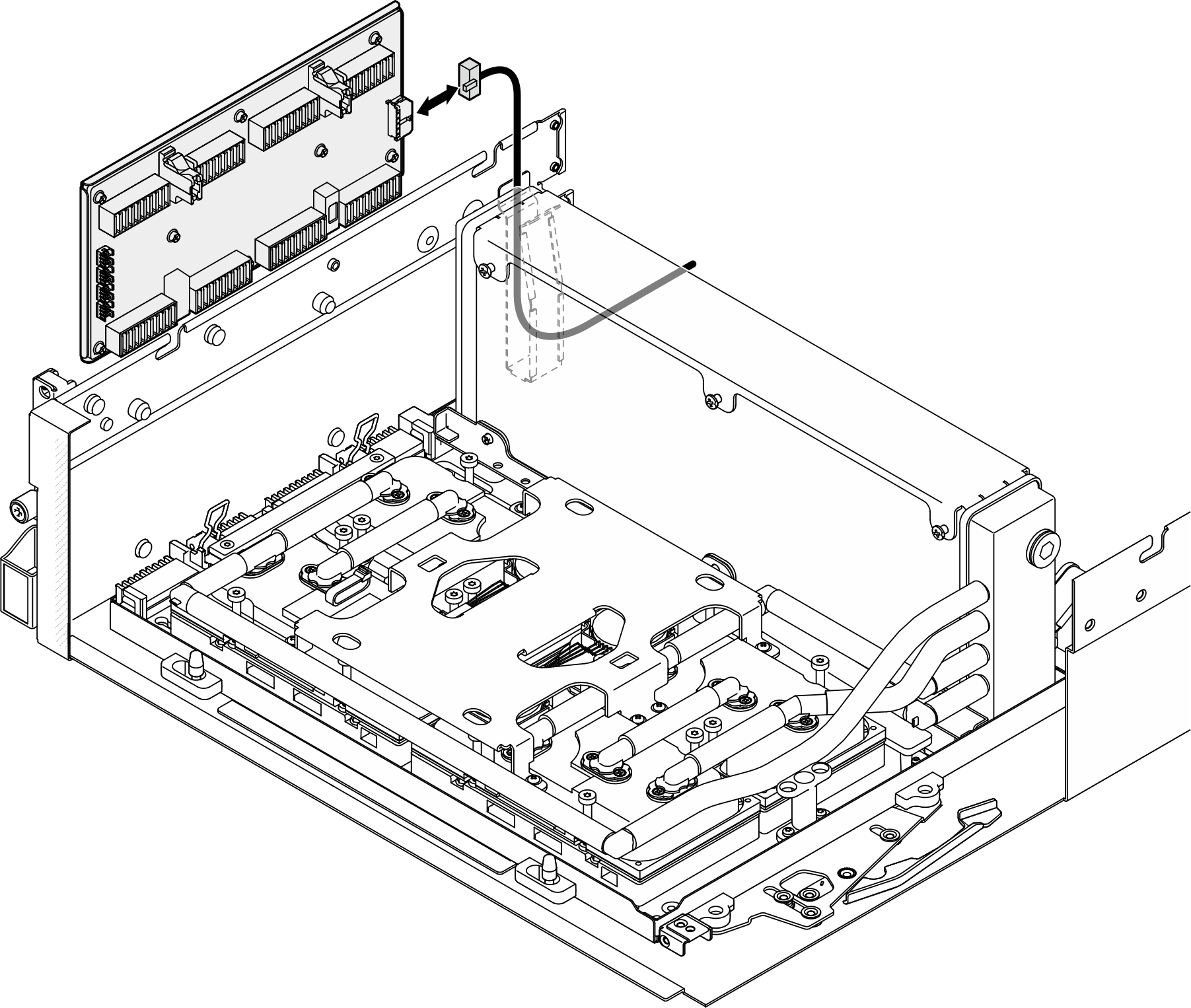
- Disconnect the power cable from the interposer card.Figure 7. Interposer card power cable disconnection
After you finish
- If you are instructed to return the component or optional device, follow all packaging instructions, and use any packaging materials for shipping that are supplied to you.
- If you plan to recycle the component:
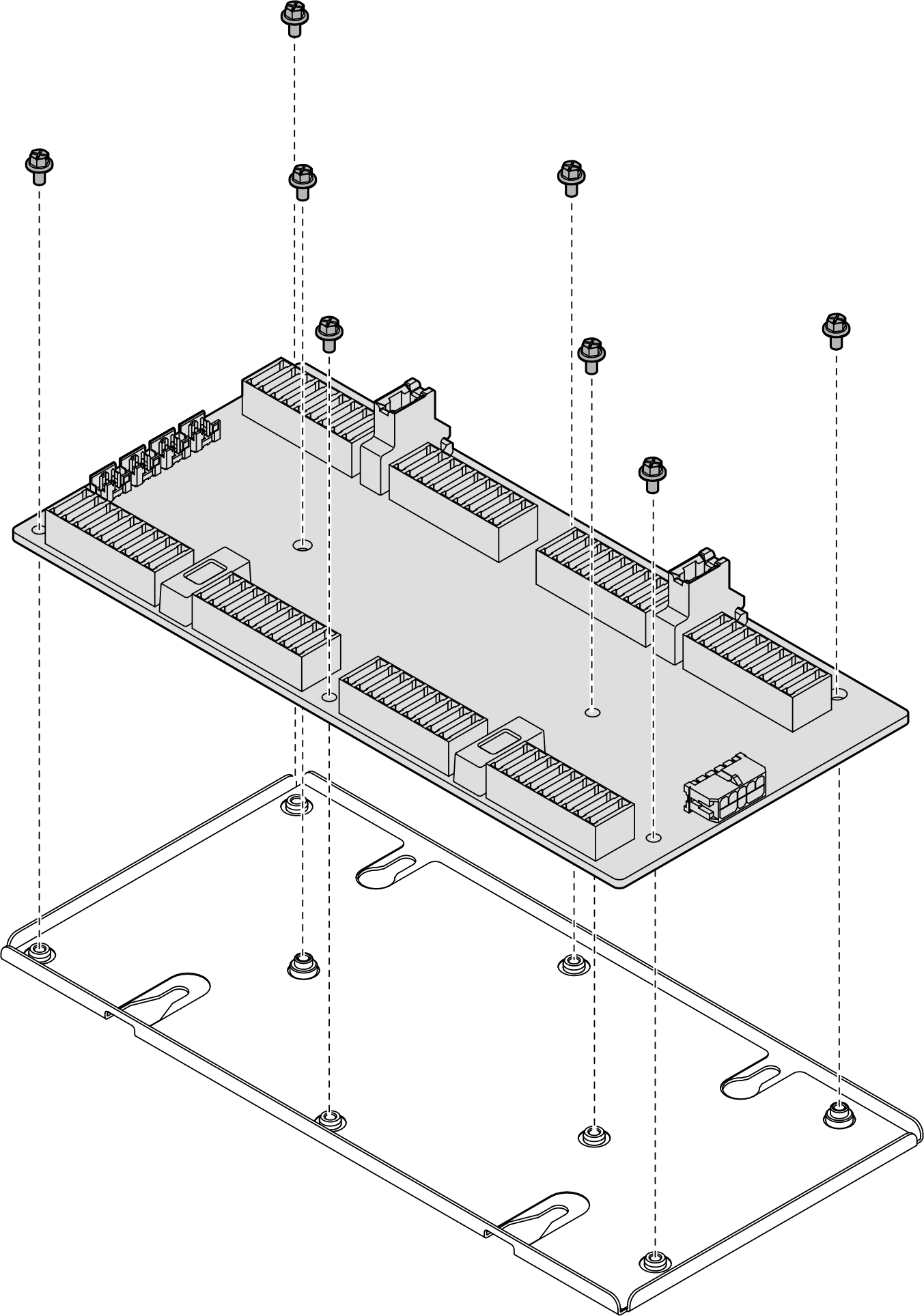
- Remove the eight screws from the interposer card to separate it from the supporting sheet metal.Figure 8. Interposer card disassembly
- Recycle the component in compliance with local regulations.
- Remove the eight screws from the interposer card to separate it from the supporting sheet metal.
Demo video
Give documentation feedback