Install a PCIe riser assembly
Follow instructions in this section to install a PCIe riser assembly.
About this task
Attention
- Read Installation Guidelines and Safety inspection checklist to ensure that you work safely.
- Touch the static-protective package that contains the component to any unpainted metal surface on the server; then, remove it from the package and place it on a static-protective surface.
- The server support up to two PCIe risers, see the following illustration for corresponding locations.Figure 1. PCIe riser locations
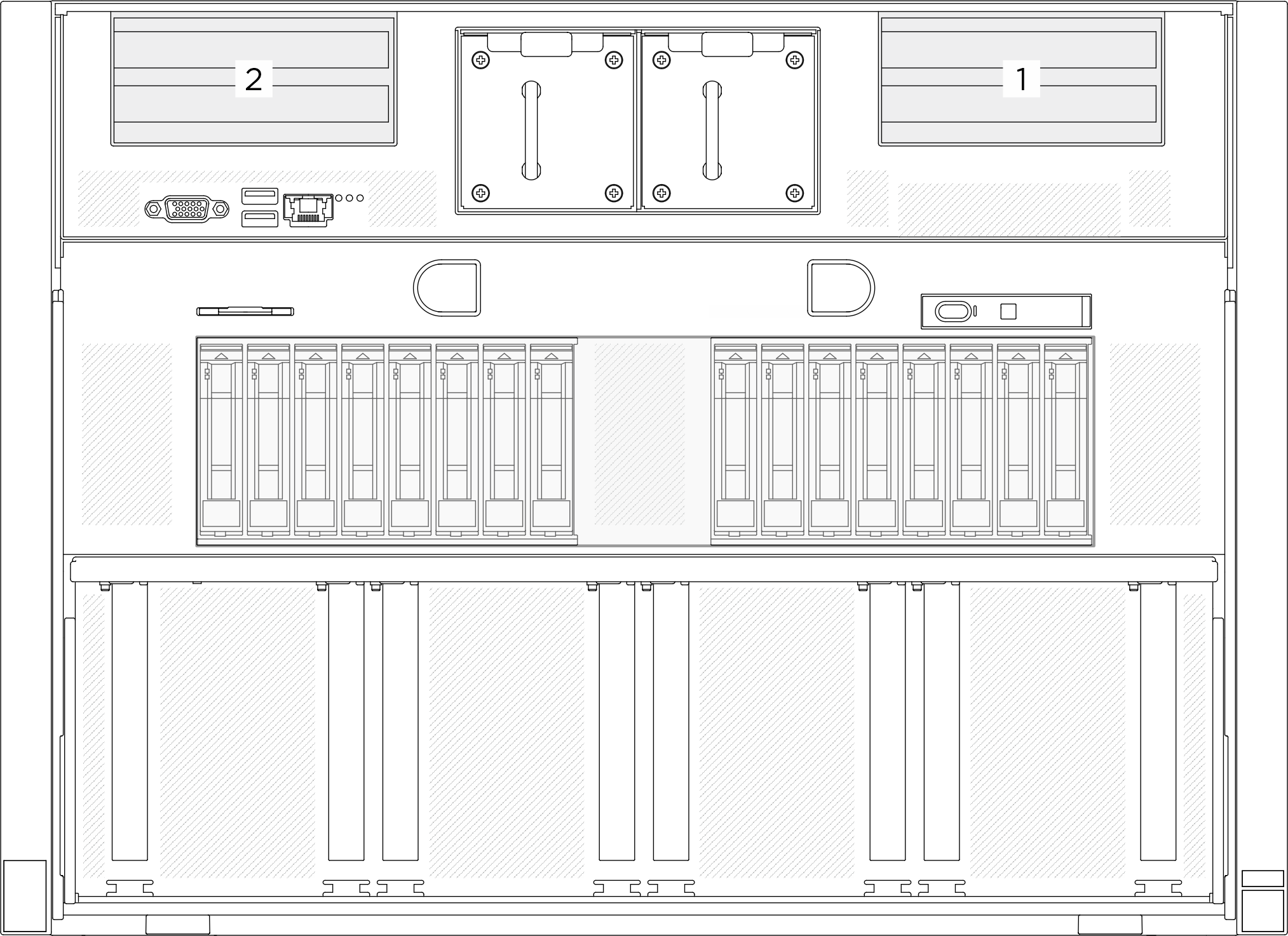
Note
The PCIe riser assembly might look different from the illustration.
Procedure
- If necessary, attach the labels to both ends of the cable(s).
 Attach the white space portion of the label to one end of the cable.
 Wrap the label around the cable and attach it to the white space portion.
- Repeat to attach the other label to the opposite end of the cable.
Figure 2. Label application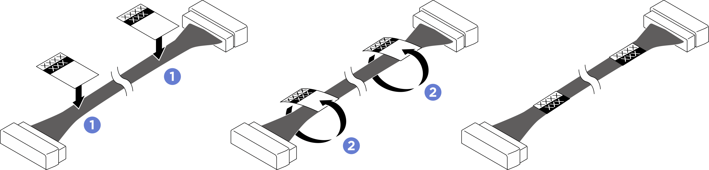 NoteSee the table below to identify the corresponding labels for the cables.
From To Label PCIe riser 1 signal connector (MCIO 1) System board: PCIe Riser 1 signal connectors (MCIO8A) - R1 MCIO 1
- MCIO 8A
PCIe riser 1 signal connector (MCIO 2) System board: PCIe Riser 1 signal connectors (MCIO8B) - R1 MCIO 2
- MCIO 8B
PCIe Riser 1 power connector (RISER PWR) System board: PCIe Riser 1 power and sideband connector (BP PWR/SIG 3) - R1 PWR
- SIG 3
PCIe riser 2 signal connector (MCIO 1) System board: PCIe Riser 2 signal connectors (MCIO4B) - R2 MCIO 1
- MCIO 4B
PCIe riser 2 signal connector (MCIO 2) System board: PCIe Riser 2 signal connectors (MCIO4A) - R2 MCIO 2
- MCIO 4A
PCIe Riser 2 power connector (RISER PWR) System board: PCIe Riser 2 power and sideband connector (BP PWR/SIG 2) - R2 PWR
- SIG 2
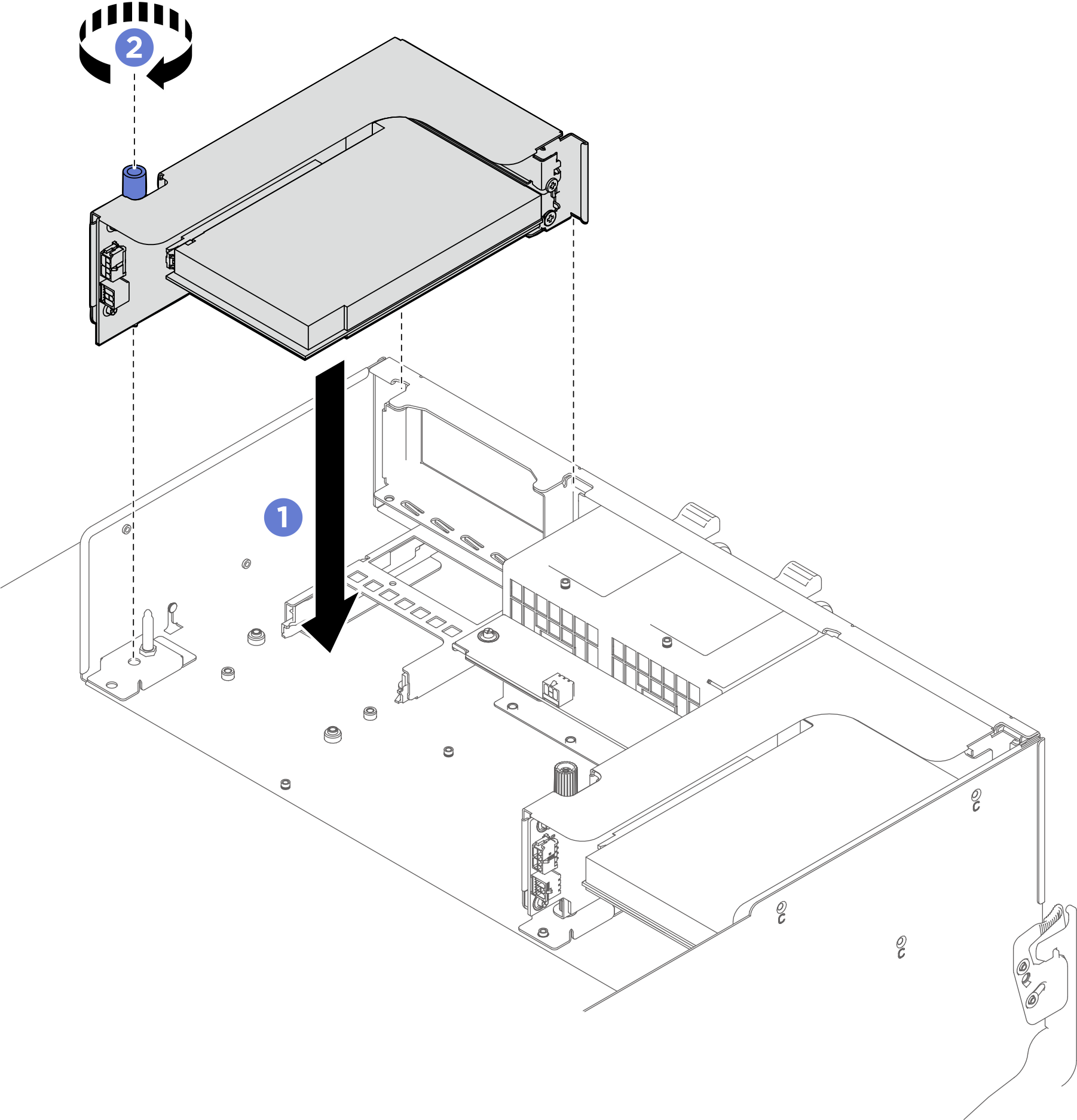
- Install the PCIe riser assembly.
- Align the guide hole on the PCIe riser with the guide post on the shuttle; then, lower the PCIe riser assembly into the shuttle.
- Fasten the thumbscrew to secure the PCIe riser assembly.Figure 3. PCIe riser assembly installation
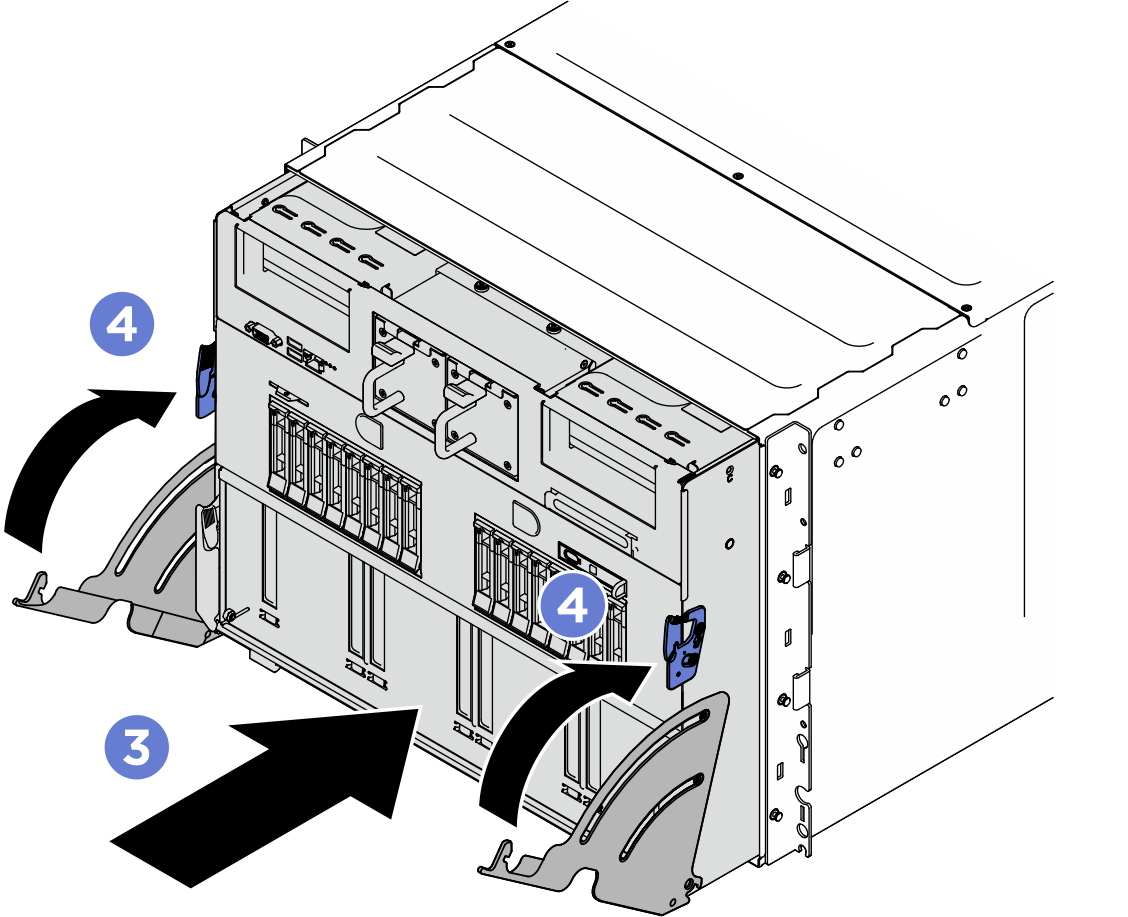
- Push the system shuttle fully into the chassis.
- Lift the two lock latches on both sides of the shuttle.
- Slide the shuttle into the chassis.
 Push the shuttle fully into the chassis.
 Rotate the two release levers until they lock into place.
Figure 4. System shuttle installation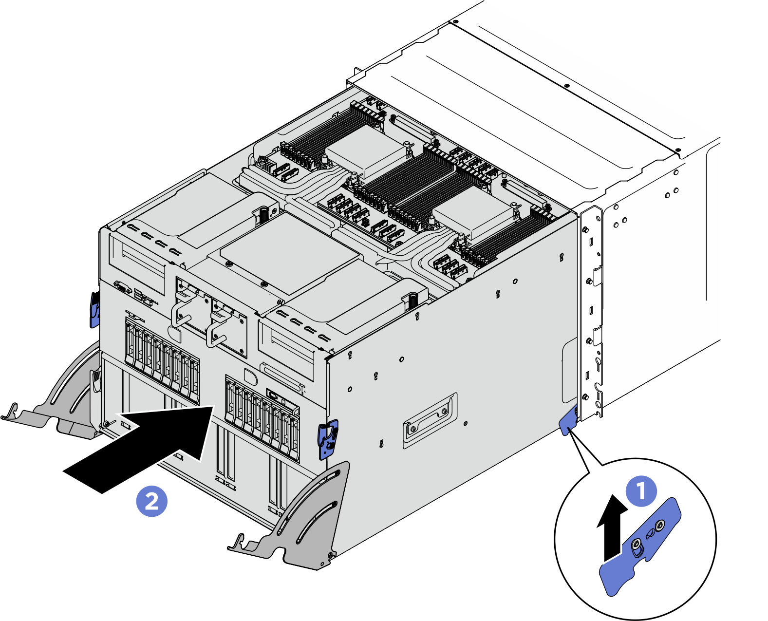
After you finish
Complete the parts replacement. See Complete the parts replacement.
Give documentation feedback