Install the system I/O board
Follow instructions in this section to install the system I/O board, also known as Datacenter Secure Control Module (DC-SCM).
About this task
Attention
- Read Installation Guidelines and Safety inspection checklist to ensure that you work safely.
- Touch the static-protective package that contains the component to any unpainted metal surface on the server; then, remove it from the package and place it on a static-protective surface.
- Prevent exposure to static electricity, which might lead to system halt and loss of data, by keeping static-sensitive components in their static-protective packages until installation, and handling these devices with an electrostatic-discharge wrist strap or other grounding system.
Firmware and driver download: You might need to update the firmware or driver after replacing a component.
Go to Drivers and Software download website for ThinkSystem SR680a V3 to see the latest firmware and driver updates for your server.
Go to Update the firmware for more information on firmware updating tools.
Procedure
 Hold the system I/O board at an angle, and insert it into the FIO/PCI cage.
 Lower the system I/O board; then, align the notches on the system I/O board with the retainers as illustrated.
 Connect the cable to the system I/O board.
 Tighten the four screws to secure the system I/O board and the cable.Figure 1. Installing system I/O board
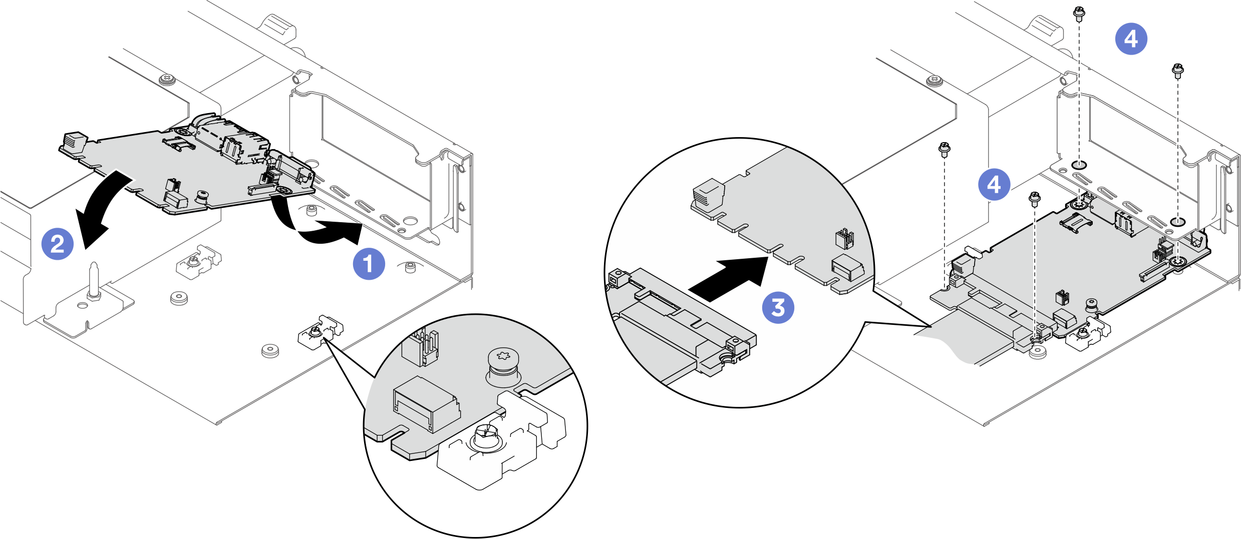
After you finish
- If applicable, reinstall the PCIe riser assembly 2. See Install a PCIe riser assembly.
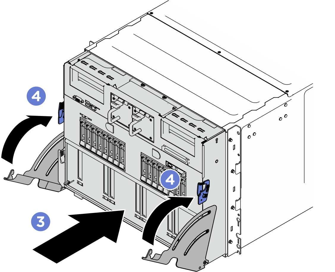
- Push the system shuttle fully into the chassis.
- Lift the two lock latches on both sides of the shuttle.
- Slide the shuttle into the chassis.
- Push the shuttle fully into the chassis.
- Rotate the two release levers until they lock into place.
Figure 2. System shuttle installation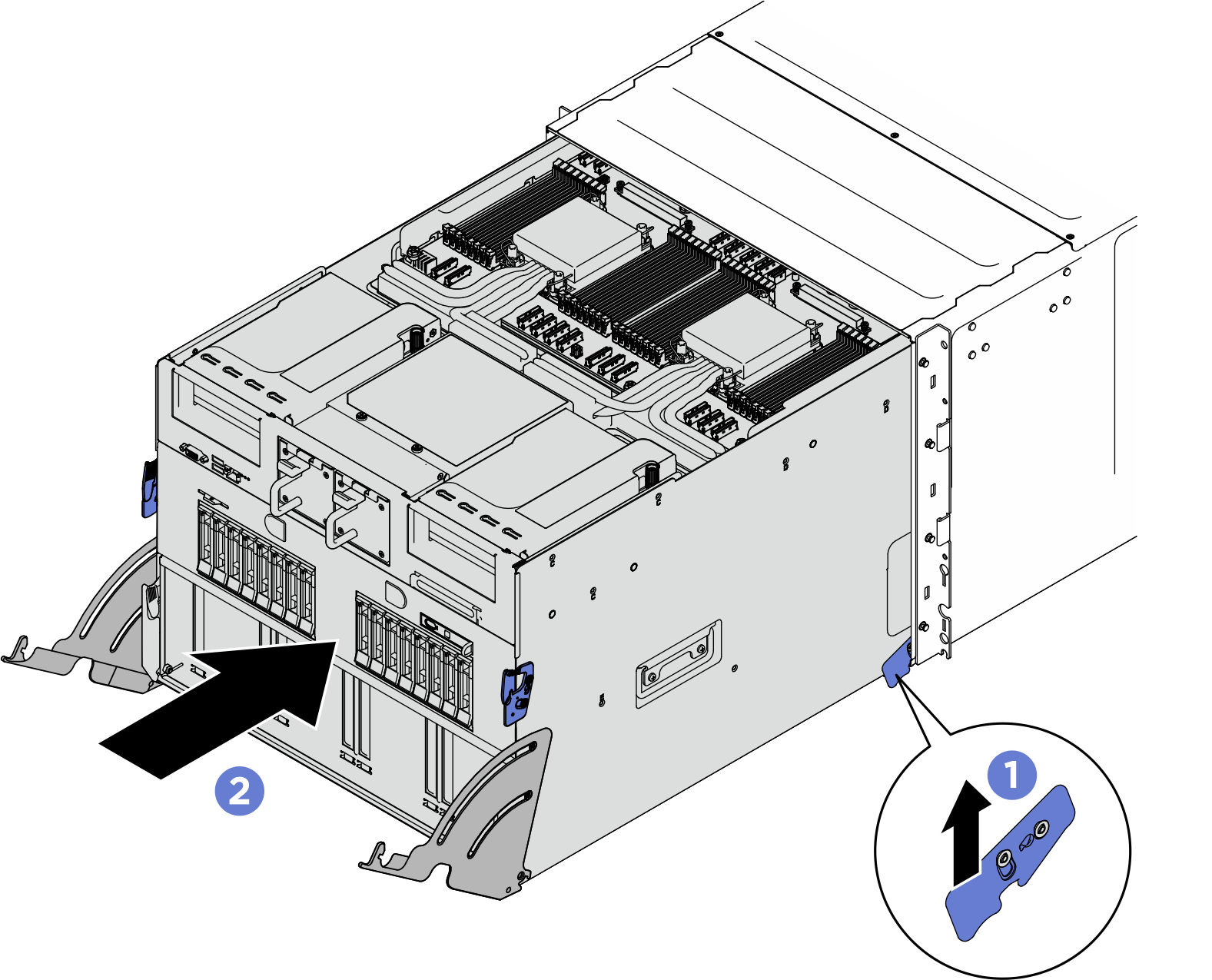
- Reconnect the power cords and any cables that you removed.
- Power on the server and any peripheral devices. See Power on the server.
- Update the UEFI firmware. (Lenovo service technicians only) See Procedure for replacing System I/O board (DC-SCM) and updating system firmware on V4 system..
- Update the XCC/LXPM/FPGA SCM/LXUM firmware. See Update the firmware.
- Perform OneCLI commands or XCC actions to restore the UEFI and XCC settings. See OneCLI commands that restore configuration settings or Using XCC to restore the BMC configuration.
- Reinstall the FoD key.
- Set the TPM policy. See Enable TPM.
- If hiding TPM or updating TPM firmware is needed, see Hide/observe TPM or Update the TPM firmware.
- Optionally, enable UEFI Secure Boot. See Enable UEFI Secure Boot.
Give documentation feedback