Remove the GPU baseboard
Follow instructions in this section to remove the GPU baseboard. The procedure must be executed by a trained technician.
About this task
Attention
- Read Installation Guidelines and Safety inspection checklist to ensure that you work safely.
- Power off the server and peripheral devices and disconnect the power cords and all external cables. See Power off the server.
- Two people and one lifting device on site that can support up to 400 lb (181 kg) are required to perform this procedure. If you do not already have a lifting device available, Lenovo offers the Genie Lift GL-8 material lift that can be purchased at Data Center Solution Configurator. Make sure to include the Foot-release brake and the Load Platform when ordering the Genie Lift GL-8 material lift.
Note
Make sure you have the required tools listed below available to properly replace the component:
- Torque screwdrivers
- Two Torx T15 extended bits (300 mm long)
- One B200 jig
Procedure
- Pull the PCIe switch shuttle to the first stop position.
 Press the two blue release latches.
 Rotate the two release levers until they are perpendicular to the PCIe switch shuttle.
 Pull the PCIe switch shuttle forward to the first stop position.AttentionTo avoid damage, push the two release levers back and ensure they lock into place after extending the PCIe switch shuttle to its first stop position.Figure 1. Pulling the PCIe switch shuttle to the first stop position
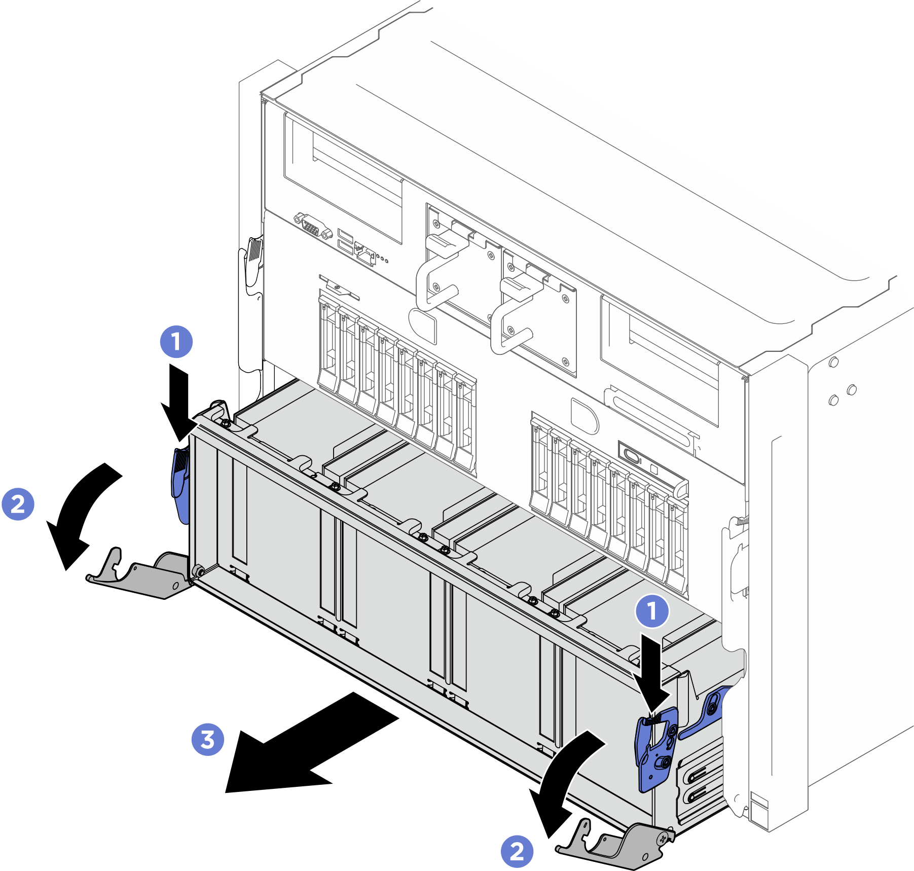
- Remove the support bracket.
- Unfasten the two screws that secure the support bracket.
- Lift the support bracket out of the system shuttle.
Figure 2. Support bracket removal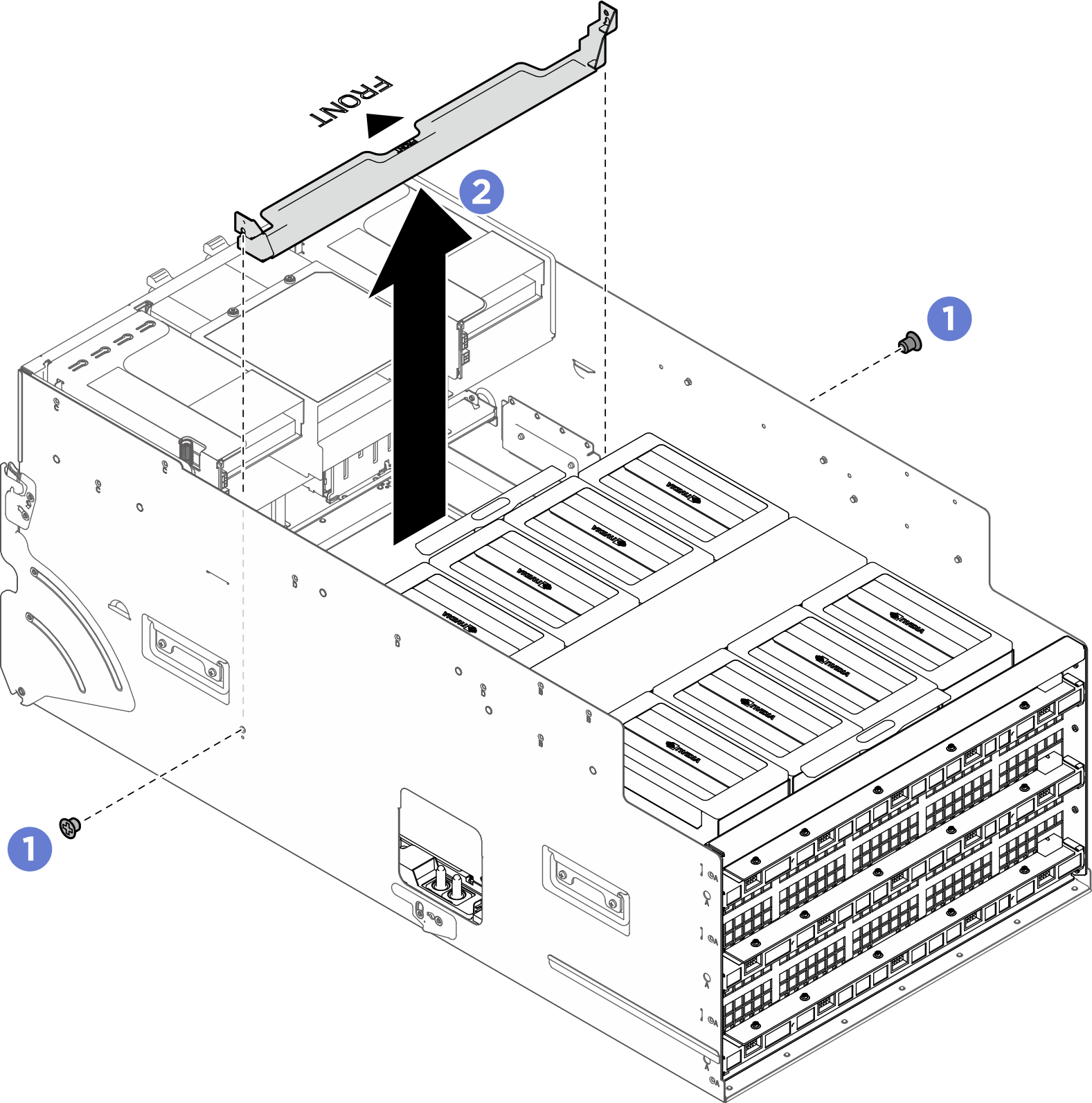
- Remove the bulkhead.
- Unfasten the eight screws marked with A on both sides of the system shuttle.
- Slide the bulkhead backward and remove it from the system shuttle.
Figure 3. Bulkhead removal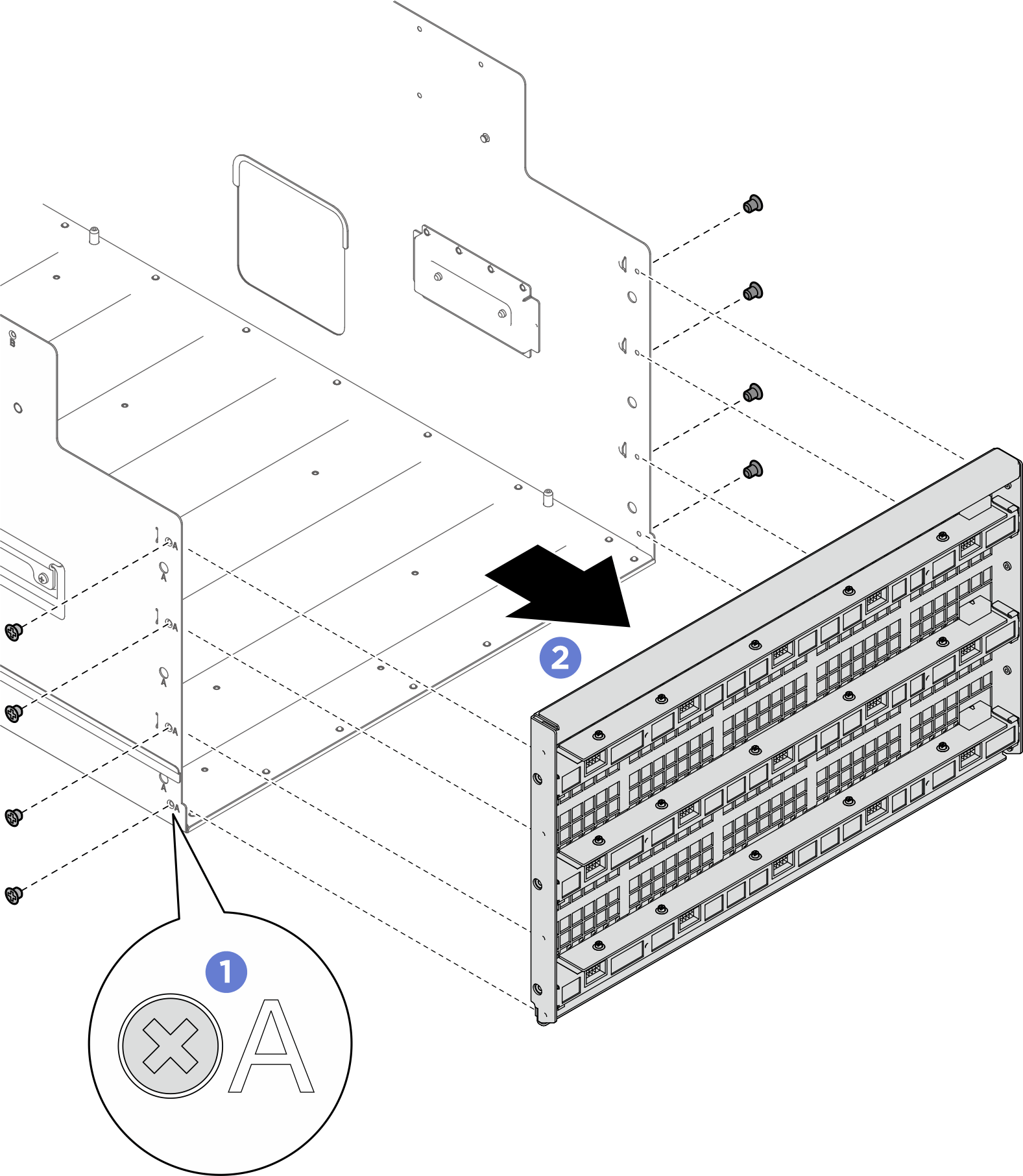
- Remove the cover from the NVSwitch heat sink.Figure 4. NVSwitch heat sink cover removal
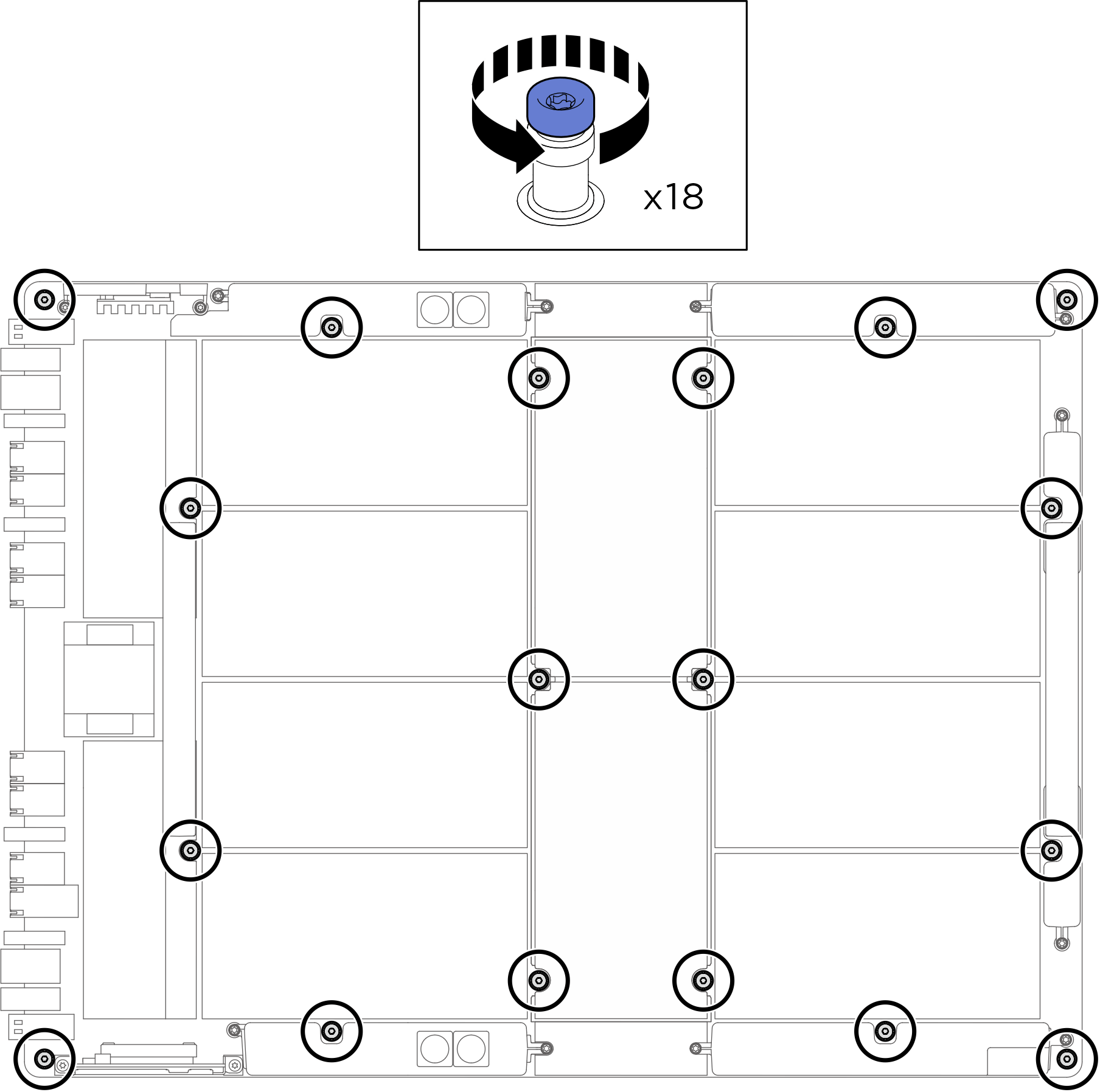
- Unfasten the eighteen Torx T15 captive screws on the GPU baseboard.NoteLoosen or tighten the screws with a torque screwdriver set to the proper torque. For reference, the torque required for the screws to be fully loosen or tighten is 0.6±0.024 newton-meters, 5.3±0.212 inch-pounds.Figure 5. Screw removal
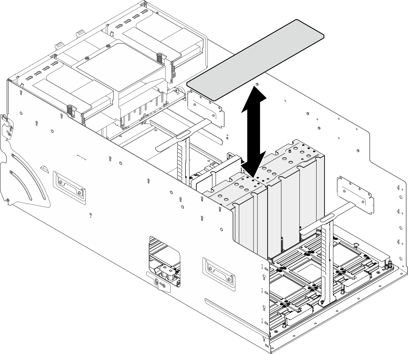
- Remove the GPU baseboard.
- Extend the two handles (1) on both sides of the GPU baseboard.
- Grasp the center of both handles (1) simultaneously and lift the GPU baseboard vertically out of the system shuttle.
Attention- Do not lift the GPU baseboard using only one handle.
- Apply even pressure to the center of the handles. Avoid applying force to just one end of a handle, as this can cause it to rotate or be damaged.
- Maintain a smooth and vertical motion. Do not apply side force to the top of the handles.
- Ensure both handles remain at the same height during the handling process.
Figure 6. GPU baseboard removal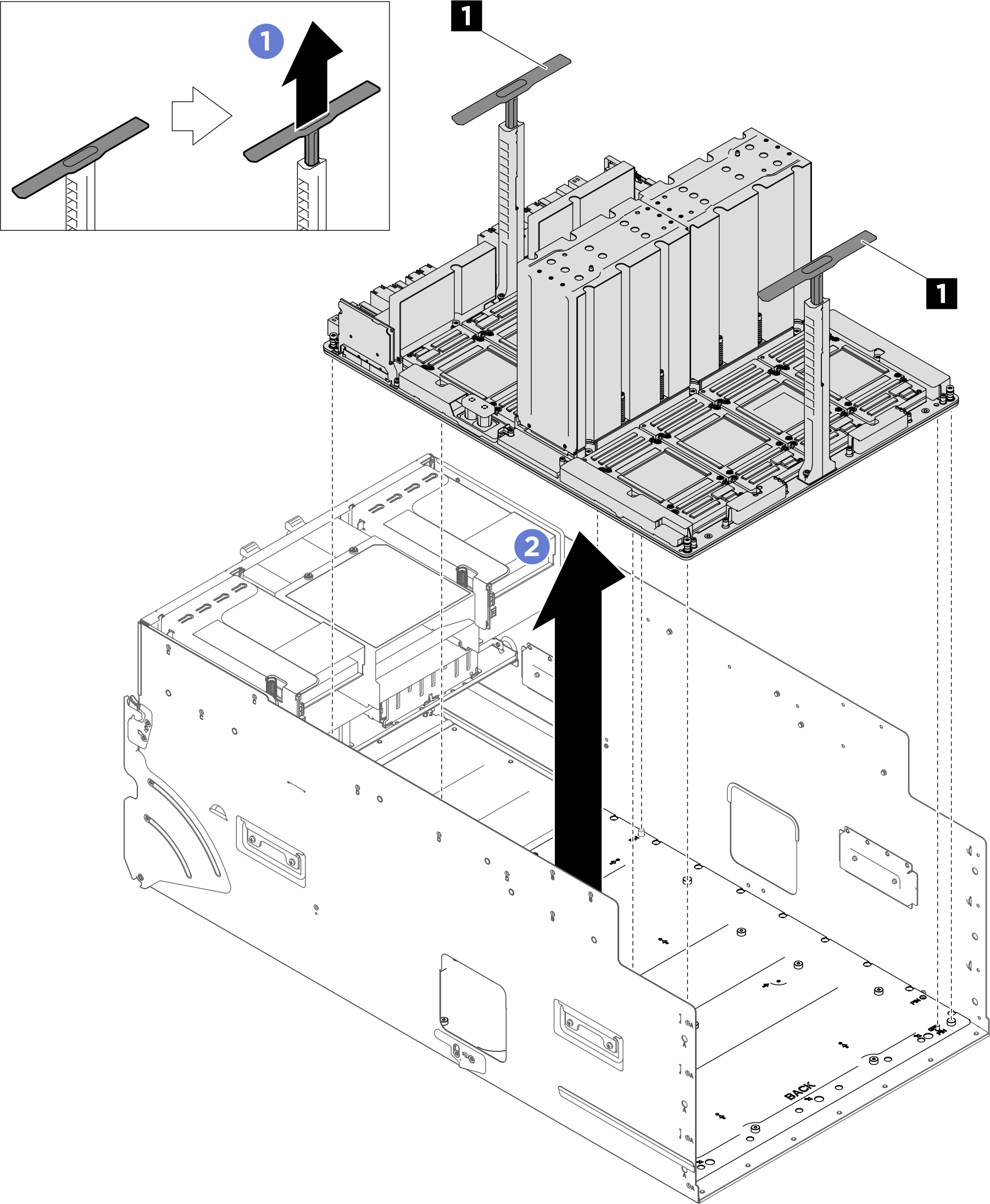
After you finish
If you are instructed to return the component or optional device, follow all packaging instructions, and use any packaging materials for shipping that are supplied to you.
Give documentation feedback