Install a hot-swap power supply unit
Follow instructions in this section to install a hot-swap power supply unit.

To avoid a shock hazard:
- To connect or disconnect -48V dc power cords when you need to remove/install redundancy power supply unit(s).
| To Connect: | To Disconnect: |
|---|---|
|
|
Never remove the cover on a power supply or any part that has this label attached. Hazardous voltage, current, and energy levels are present inside any component that has this label attached. There are no serviceable parts inside these components. If you suspect a problem with one of these parts, contact a service technician.
About this task
- Read Installation Guidelines and Safety inspection checklist to ensure that you work safely.
- Touch the static-protective package that contains the component to any unpainted metal surface on the server; then, remove it from the package and place it on a static-protective surface.
Procedure
- If there is a power-supply-unit filler installed, remove it.Figure 1. Removing the power-supply-unit filler
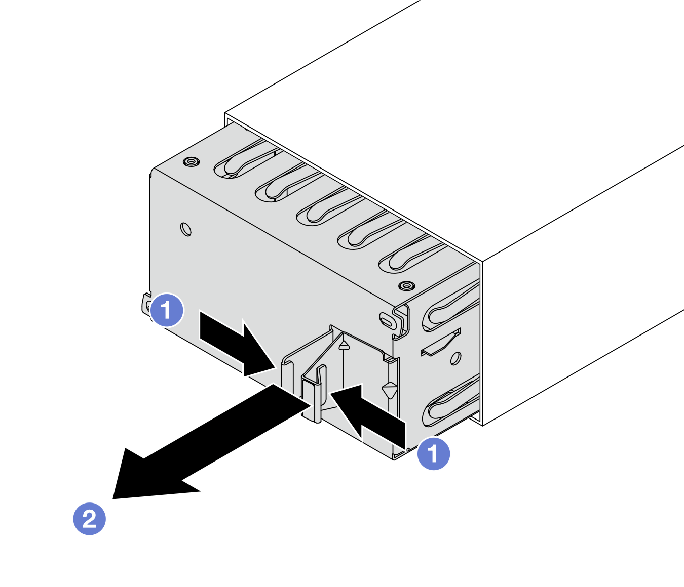
 Pinch the latches to unlock the power-supply-unit filler.
 Pull out the filler.
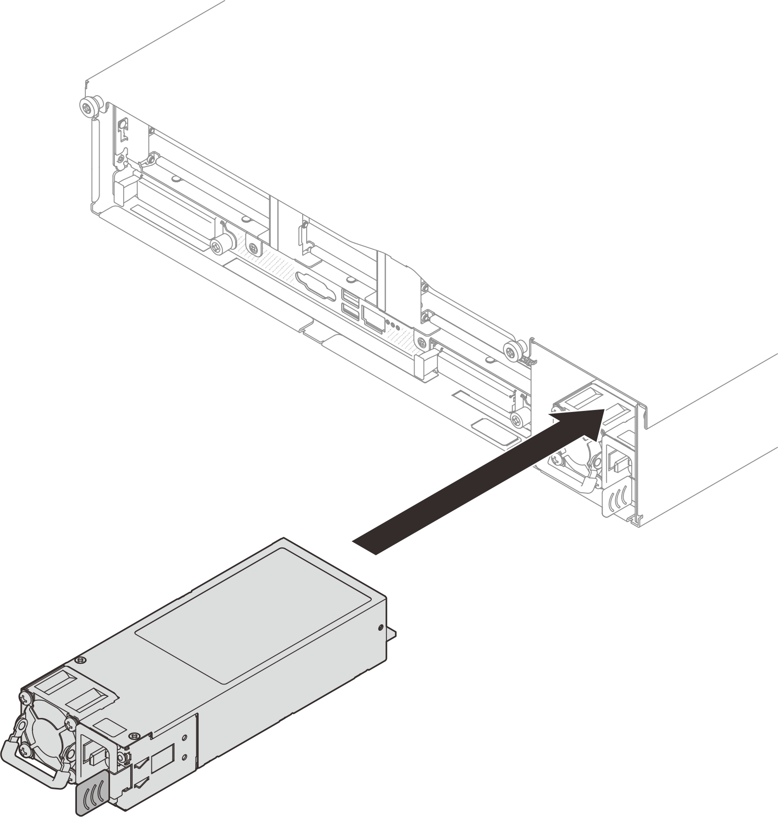
- Make sure the label on the power supply is facing up; then, grasp the handle and slide it into the power supply bay until it clicks into place.Figure 2. Power supply unit installationNote
Power supply units in the chassis must have the same wattage, vendor, and part number (or alternate part number).
PSU with a release tab is a hot-swap PSU. The color of the release tab does not affect the serviceability of the PSU.
- Connect the power supply unit to a properly grounded electrical outlet.
For 240 V DC power supply units:
Turn off the server.
Connect one end of the power cord to the power connector on the power supply unit.
Connect the other end of the power cord to a properly grounded electrical outlet.
For AC power supply units:
Connect one end of the power cord to the power connector on the power supply unit.
Connect the other end of the power cord to a properly grounded electrical outlet.
For –48V DC power supply units:
Use a slotted screwdriver to loosen three captive screws on the power supply terminal block.
- Check the type label on the power supply block and each power cord.
Type PSU terminal block Power cord Input 
-Vin Ground 
GND Input 
RTN Face the groove side of each power cord pin upwards, and then plug the pins into corresponding holes on the power block. Use the table above for guidance to ensure that the pins find correct slots.
Tighten the captive screws on the power block. Ensure that the screws and cord pins are secured in place and no bare metal parts are shown.
Connect the other end of the cables to a properly grounded electrical outlet. Ensure that the cable ends find correct outlets.
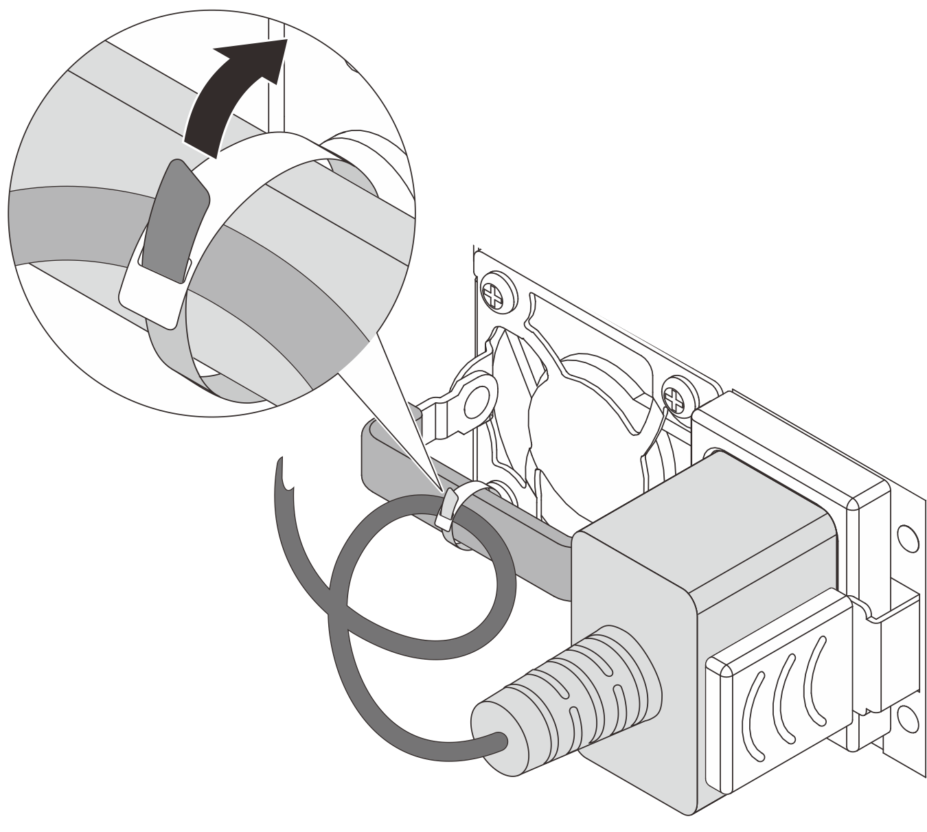
- Make sure the power supply unit handle is perpendicular to the power supply unit; then, tie the power cord to the handle with the pre-attached strap as shown below.Figure 3. Routing and tying power cord
After you finish
- Pull the handle to see if the power supply unit is properly installed. If it slides out, reinstall it.
- Complete the parts replacement. See Complete the parts replacement.
- If the server is turned off, turn on the server. Ensure that:
Both LEDs on the CRPS Premium power supply unit are lit green, indicating that the power supply unit is operating properly.
The LED on the CRPS power supply unit is lit green, indicating that the power supply unit is operating properly.
Demo video