Install the system board (trained technician only)
Follow this procedure to install the system board. This procedure must be executed by a trained technician.
About this task
Read Safety inspection checklist and Installation guidelines to ensure that you work safely.
Touch the static-protective package that contains the component to any unpainted metal surface on the server; then, remove it from the package and place it on a static-protective surface.
- A video of this procedure is available at YouTube.
Procedure
- Install the system board.
 Tilt the system board, and align the connectors with the corresponding opening on the front of the chassis. Then, gently lower the system board into the chassis, and insert the connectors into the slot on the front of the chassis.
 Slide the system board toward the rear of the chassis until the system board is secured in place.Figure 1. Installing the system board into the chassis
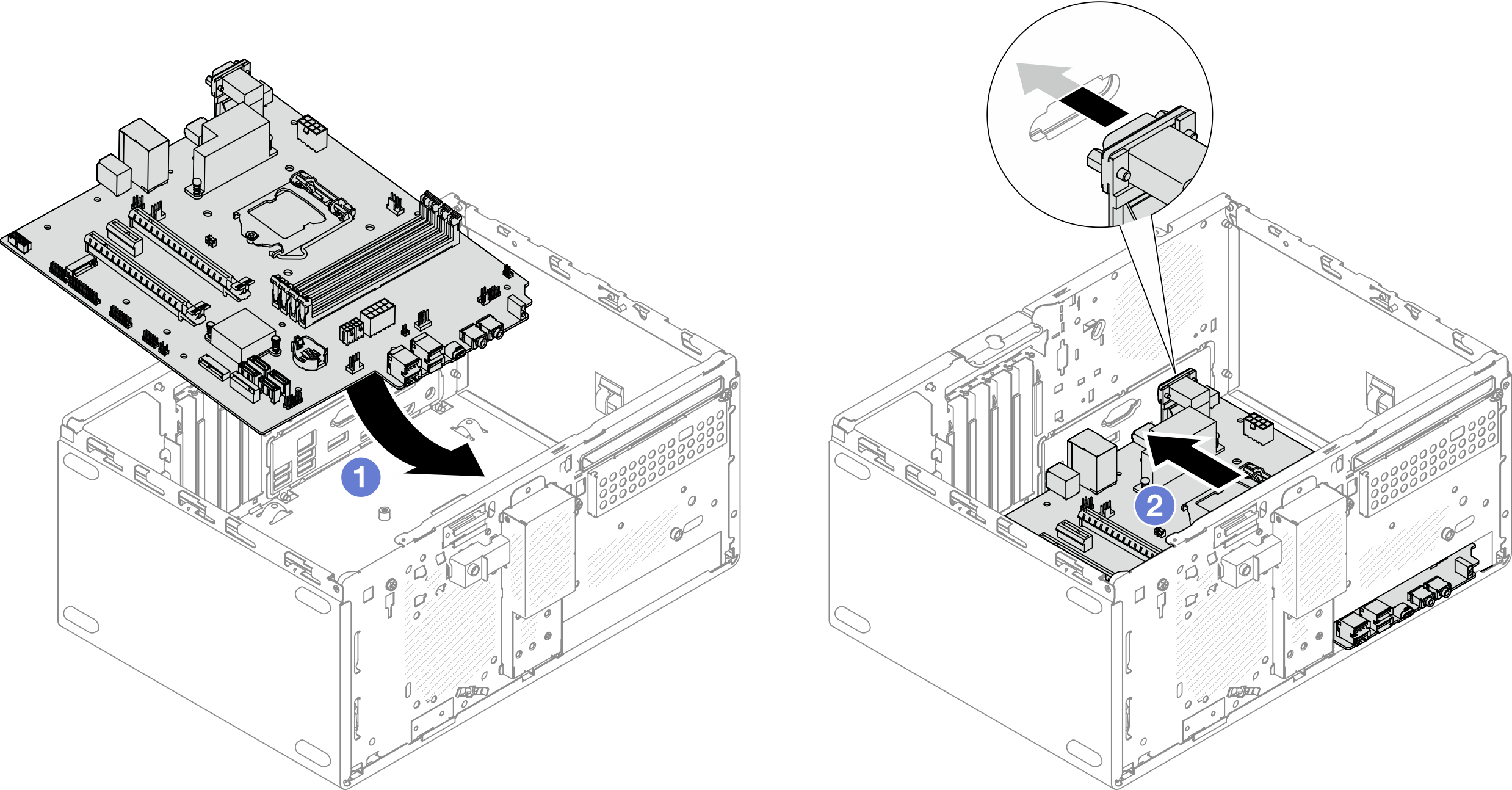
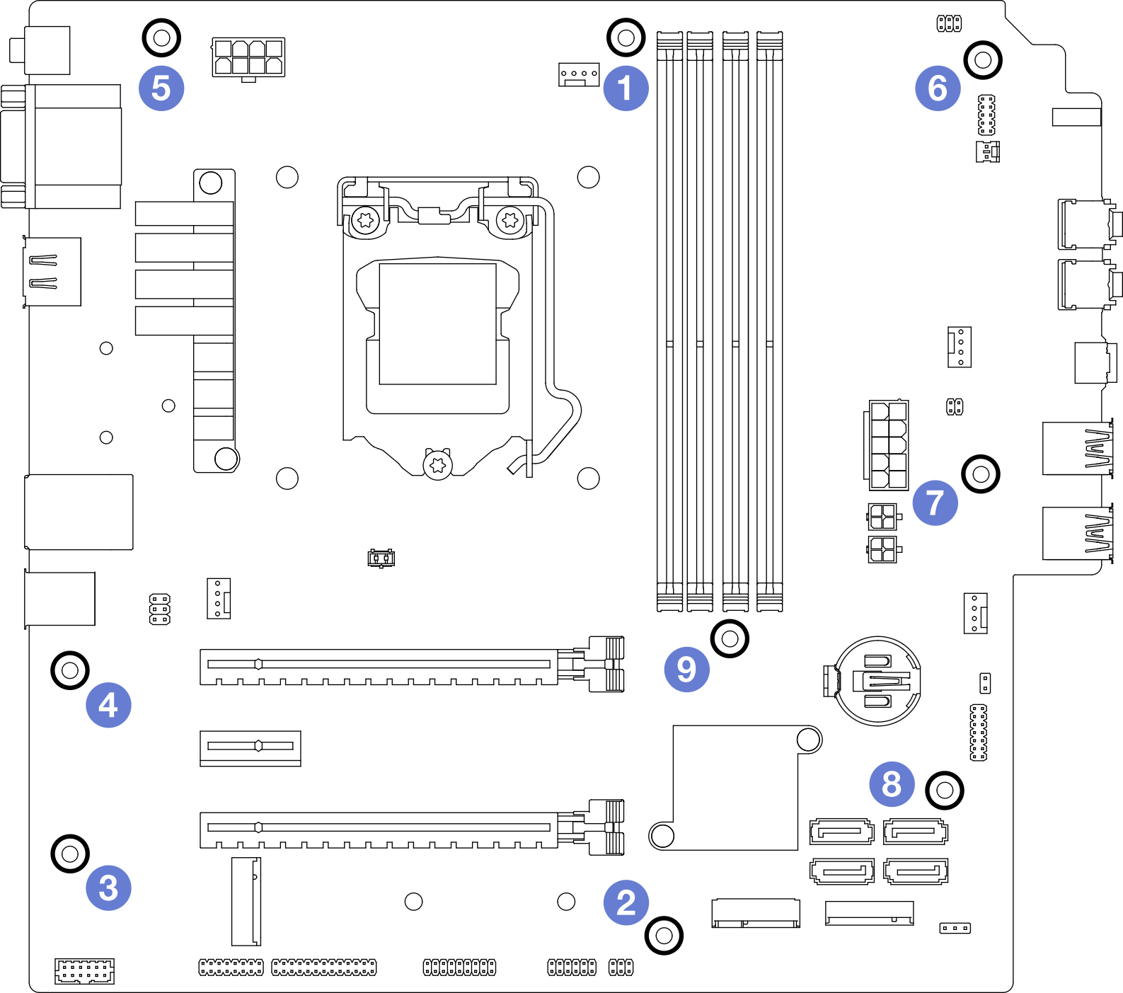
- Secure the system board to the chassis with nine screws in the sequence shown on the illustration below.Figure 2. System-board screws installation sequence
Make sure the CMOS battery is installed on the system board, see Install the CMOS battery (CR2032).
Reinstall the processor. see Install the processor (trained technician only).
Reinstall the heat sink and fan module, see Install the heat sink and the fan module (trained technician only)
Reinstall the memory modules. see Install a memory module.
Reinstall the front panel, see Install the front panel.
If necessary, reinstall the PCIe adapters, see Remove a PCIe adapter.
If necessary, reinstalled the M.2 drive, see Install an M.2 drive.
If applicable, reinstall the rear fan, see Install the fan (front and rear).
If applicable, reinstall the cage bar, see Step 1 in Install the server cover.
If necessary, reinstall the optical drive cage, see Install the optical drive cage.
If necessary, reinstall the optical drive, see Install an optical drive.
Reinstall the front bezel, see Install the front bezel.
Reconnect all the cables that were disconnected.
Complete the parts replacement, see Complete the parts replacement.
Update UEFI BIOS, VPD, and security locked procedures. See ST50 V2 Tip HT513859 (Not including PRC) or ST50 V2 Tip HT513863 (PRC only).
Important Update the system firmware and device driver.
Go to Lenovo Support - ST50 V2 (including drivers and software) to see the latest firmware and driver updates for your server.
Go to Update the firmware for more information on firmware updating tools.