Remove the system board (trained technician only)
Follow this procedure to remove the system board. This procedure must be executed by a trained technician.
About this task
Record all the settings in the Setup Utility, as you might have to re-enter these settings after replacing the system board.
Read Safety inspection checklist and Installation guidelines to ensure that you work safely.
Turn off the server and peripheral devices, and disconnect the power cords and all external cables, see Power off the server.
If the server is in a rack, remove it from the rack. See Remove the server from the rails.
Remove any locking device that secures the server, such as a Kensington lock or a padlock.
Place the server on its side with the cover up.
- A video of this procedure is available at YouTube.
Procedure
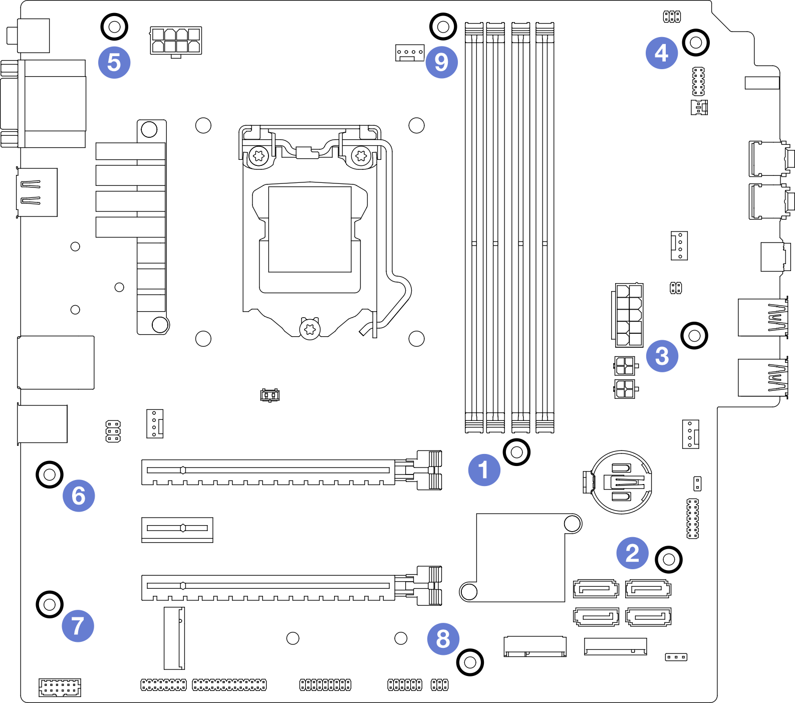
- Remove the nine screws that secure the system board in the sequence shown on the illustration below. Keep the screws for future use.Figure 1. System-board screws removal sequence
- Remove the system board from the chassis.
 Slide the system board toward the front of the server to release the serial port connector from the chassis.
 Gently grasp the system board by the edges; then, tilt the system board, and remove it from the chassis.Figure 2. Removing the system board from the chassis
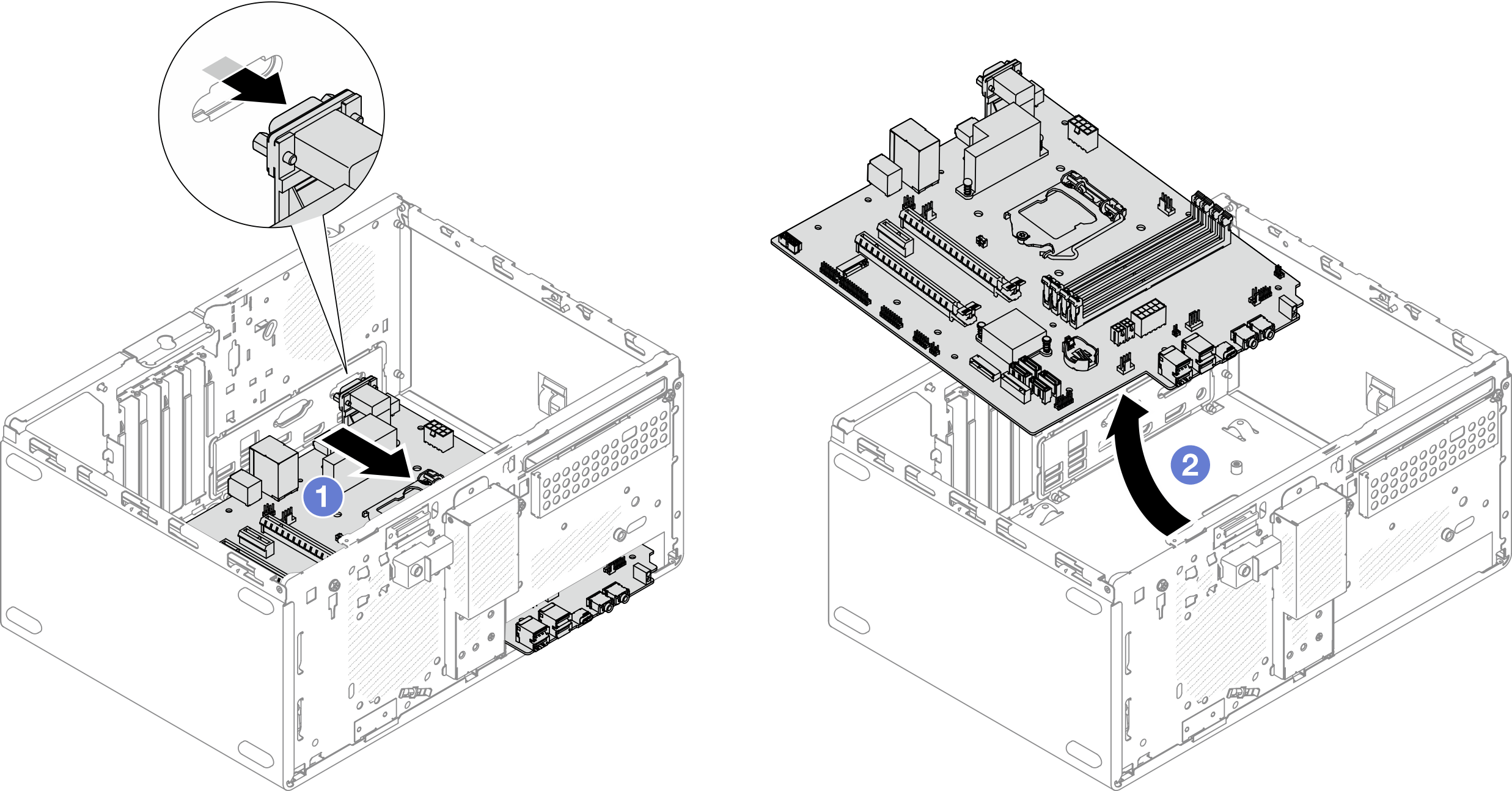
Install a new system board, see Install the system board (trained technician only).
If you are instructed to return the component or optional device, follow all packaging instructions, and use any packaging materials for shipping that are supplied to you.